|
CMSIS-Driver
Version 2.8.0
Peripheral Interface for Middleware and Application Code
|
|
CMSIS-Driver
Version 2.8.0
Peripheral Interface for Middleware and Application Code
|
Driver API for Serial Audio Interface (Driver_SAI.h) More...
Content | |
| Status Error Codes | |
| Negative values indicate errors (SAI has specific codes in addition to common Status Error Codes). | |
| SAI Events | |
| The SAI driver generates call back events that are notified via the function ARM_SAI_SignalEvent. | |
| SAI Control Codes | |
| Many parameters of the SAI driver are configured using the ARM_SAI_Control function. | |
Data Structures | |
| struct | ARM_DRIVER_SAI |
| Access structure of the SAI Driver. More... | |
| struct | ARM_SAI_CAPABILITIES |
| SAI Driver Capabilities. More... | |
| struct | ARM_SAI_STATUS |
| SAI Status. More... | |
Typedefs | |
| typedef void(* | ARM_SAI_SignalEvent_t )(uint32_t event) |
| Pointer to ARM_SAI_SignalEvent : Signal SAI Event. More... | |
Functions | |
| ARM_DRIVER_VERSION | ARM_SAI_GetVersion (void) |
| Get driver version. More... | |
| ARM_SAI_CAPABILITIES | ARM_SAI_GetCapabilities (void) |
| Get driver capabilities. More... | |
| int32_t | ARM_SAI_Initialize (ARM_SAI_SignalEvent_t cb_event) |
| Initialize SAI Interface. More... | |
| int32_t | ARM_SAI_Uninitialize (void) |
| De-initialize SAI Interface. More... | |
| int32_t | ARM_SAI_PowerControl (ARM_POWER_STATE state) |
| Control SAI Interface Power. More... | |
| int32_t | ARM_SAI_Send (const void *data, uint32_t num) |
| Start sending data to SAI transmitter. More... | |
| int32_t | ARM_SAI_Receive (void *data, uint32_t num) |
| Start receiving data from SAI receiver. More... | |
| uint32_t | ARM_SAI_GetTxCount (void) |
| Get transmitted data count. More... | |
| uint32_t | ARM_SAI_GetRxCount (void) |
| Get received data count. More... | |
| int32_t | ARM_SAI_Control (uint32_t control, uint32_t arg1, uint32_t arg2) |
| Control SAI Interface. More... | |
| ARM_SAI_STATUS | ARM_SAI_GetStatus (void) |
| Get SAI status. More... | |
| void | ARM_SAI_SignalEvent (uint32_t event) |
| Signal SAI Events. More... | |
Driver API for Serial Audio Interface (Driver_SAI.h)
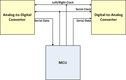
The Serial Audio Interface (SAI) implements a synchronous serial bus interface for connecting digital audio devices. It is by far the most common mechanism used to transfer two channels of audio data between devices within a system. SAI can transfer digital audio using various protocols:
Block Diagram
SAI API
The following header files define the Application Programming Interface (API) for the SAI interface:
The driver implementation is a typical part of the Device Family Pack (DFP) that supports the peripherals of the microcontroller family.
Driver Functions
The driver functions are published in the access struct as explained in Common Driver Functions
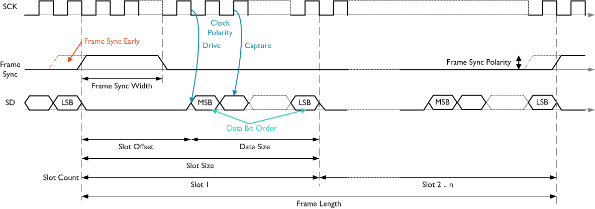
Integrated Interchip Sound (I2S) is a serial bus interface that connects digital audio devices together. It was introduced by Philips (now NXP) in the late 80's and last revised 1996. It uses pulse code modulation to exchange the audio data between the devices. The following timing diagram explains the operation:
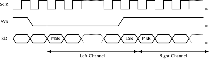
I2S separates the clock (SCK) from the serial data (SD), resulting in a lower jitter. A complete audio data frame consists of two slots, one for the left channel and one for the right. The slot size equals the data size. The word select (WS) line lets the device know whether the left channel (WS is low) or the right channel (WS is high) is currently being transmitted. WS has a 50% duty-cycle signal that has the same frequency as the sample frequency. It is an early signal, meaning that the WS line changes one clock cycle before the actual data (SD) is transmitted (left or right). The data on SD is always transmitted MSB first and can have a data size of 8 up to 32 bits.
In terms of the CMSIS-Driver for SAI, the I2S protocol can be described as follows:
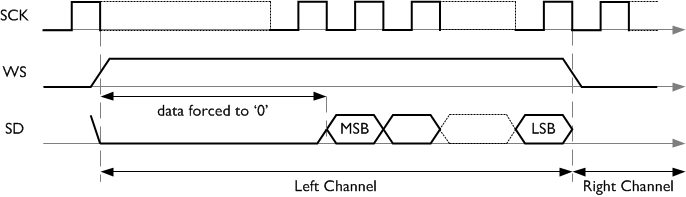
MSB Justified is much like I2S, with a few differences:

Unlike I2S, in MSB Justified the word select (WS) signals the left channel when it is active high and the right channel, when it is active low. The signal changes when the first actual SD data is available. It might happen that a frame (left or right) is not fully filled with data. In this case, all data after the LSB is forced to zero.
In terms of the CMSIS-Driver for SAI, the MSB Justified protocol can be described as follows:
LSB Justified is much like MSB Justified, with the single difference that the padding 0's are sent before the first actual data (MSB on SD):
In terms of the CMSIS-Driver for SAI, the LSB Justified protocol can be described as follows:
Pulse Code Modulation (PCM) differs to the previous protocols in a few ways:
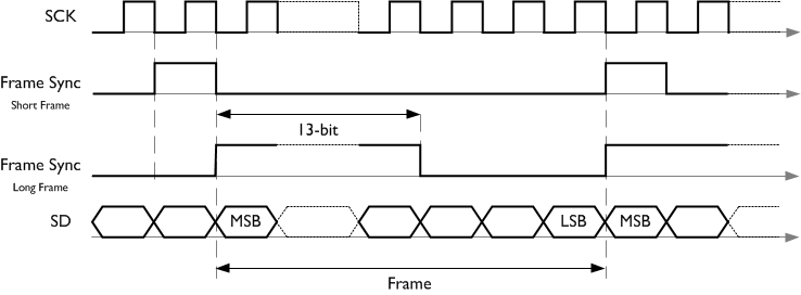
In terms of the CMSIS-Driver for SAI, the PCM protocol can be described as follows:
PCM Short Frame
PCM Long Frame
Audio Codec '97 was developed by Intel. It is composed of five wires: the clock (12.288 MHz), a sync signal, a reset signal, and two data wires: sdata_out (contains the AC97 output) and sdata_in (contains the CODEC output). For more information, consult the standard documentation.
Using the control structs of the CMSIS-Driver SAI, it is possible to create support for nearly all serial audio protocols that are available today.
The following properties can be configured for a user protocol:
For more information, refer to ARM_SAI_Control that explains the different configuration options in more detail.
| struct ARM_DRIVER_SAI |
Access structure of the SAI Driver.
The functions of the SAI driver are accessed by function pointers exposed by this structure. Refer to Common Driver Functions for overview information.
Each instance of an SAI interface provides such an access structure. The instance is identified by a postfix number in the symbol name of the access structure, for example:
A middleware configuration setting allows connecting the middleware to a specific driver instance Driver_SAIn. The default is 0, which connects a middleware to the first instance of a driver.
Data Fields | |
| ARM_DRIVER_VERSION(* | GetVersion )(void) |
| Pointer to ARM_SAI_GetVersion : Get driver version. More... | |
| ARM_SAI_CAPABILITIES(* | GetCapabilities )(void) |
| Pointer to ARM_SAI_GetCapabilities : Get driver capabilities. More... | |
| int32_t(* | Initialize )(ARM_SAI_SignalEvent_t cb_event) |
| Pointer to ARM_SAI_Initialize : Initialize SAI Interface. More... | |
| int32_t(* | Uninitialize )(void) |
| Pointer to ARM_SAI_Uninitialize : De-initialize SAI Interface. More... | |
| int32_t(* | PowerControl )(ARM_POWER_STATE state) |
| Pointer to ARM_SAI_PowerControl : Control SAI Interface Power. More... | |
| int32_t(* | Send )(const void *data, uint32_t num) |
| Pointer to ARM_SAI_Send : Start sending data to SAI Interface. More... | |
| int32_t(* | Receive )(void *data, uint32_t num) |
| Pointer to ARM_SAI_Receive : Start receiving data from SAI Interface. More... | |
| uint32_t(* | GetTxCount )(void) |
| Pointer to ARM_SAI_GetTxCount : Get transmitted data count. More... | |
| uint32_t(* | GetRxCount )(void) |
| Pointer to ARM_SAI_GetRxCount : Get received data count. More... | |
| int32_t(* | Control )(uint32_t control, uint32_t arg1, uint32_t arg2) |
| Pointer to ARM_SAI_Control : Control SAI Interface. More... | |
| ARM_SAI_STATUS(* | GetStatus )(void) |
| Pointer to ARM_SAI_GetStatus : Get SAI status. More... | |
| ARM_DRIVER_VERSION(* GetVersion)(void) |
Pointer to ARM_SAI_GetVersion : Get driver version.
| ARM_SAI_CAPABILITIES(* GetCapabilities)(void) |
Pointer to ARM_SAI_GetCapabilities : Get driver capabilities.
| int32_t(* Initialize)(ARM_SAI_SignalEvent_t cb_event) |
Pointer to ARM_SAI_Initialize : Initialize SAI Interface.
| int32_t(* Uninitialize)(void) |
Pointer to ARM_SAI_Uninitialize : De-initialize SAI Interface.
| int32_t(* PowerControl)(ARM_POWER_STATE state) |
Pointer to ARM_SAI_PowerControl : Control SAI Interface Power.
| int32_t(* Send)(const void *data, uint32_t num) |
Pointer to ARM_SAI_Send : Start sending data to SAI Interface.
| int32_t(* Receive)(void *data, uint32_t num) |
Pointer to ARM_SAI_Receive : Start receiving data from SAI Interface.
| uint32_t(* GetTxCount)(void) |
Pointer to ARM_SAI_GetTxCount : Get transmitted data count.
| uint32_t(* GetRxCount)(void) |
Pointer to ARM_SAI_GetRxCount : Get received data count.
| int32_t(* Control)(uint32_t control, uint32_t arg1, uint32_t arg2) |
Pointer to ARM_SAI_Control : Control SAI Interface.
| ARM_SAI_STATUS(* GetStatus)(void) |
Pointer to ARM_SAI_GetStatus : Get SAI status.
| struct ARM_SAI_CAPABILITIES |
SAI Driver Capabilities.
An SAI driver can be implemented with different capabilities (for example protocol support). The data fields of this structure encode the capabilities implemented by this driver. If a certain hardware peripheral is not able to handle one of the protocols directly (not advertised using ARM_SAI_CAPABILITIES), then it might be possible to implement it using the User Defined Protocol (if supported).
Returned by:
| Data Fields | ||
|---|---|---|
| uint32_t | asynchronous: 1 | supports asynchronous Transmit/Receive |
| uint32_t | synchronous: 1 | supports synchronous Transmit/Receive |
| uint32_t | protocol_user: 1 | supports user defined Protocol |
| uint32_t | protocol_i2s: 1 | supports I2S Protocol |
| uint32_t | protocol_justified: 1 | supports MSB/LSB justified Protocol |
| uint32_t | protocol_pcm: 1 | supports PCM short/long frame Protocol |
| uint32_t | protocol_ac97: 1 | supports AC'97 Protocol |
| uint32_t | mono_mode: 1 | supports Mono mode |
| uint32_t | companding: 1 | supports Companding |
| uint32_t | mclk_pin: 1 | supports MCLK (Master Clock) pin |
| uint32_t | event_frame_error: 1 | supports Frame error event: ARM_SAI_EVENT_FRAME_ERROR |
| uint32_t | reserved: 21 | Reserved (must be zero) |
| struct ARM_SAI_STATUS |
SAI Status.
Structure with information about the status of the SAI. The data fields encode busy flags and error flags.
Returned by:
| ARM_SAI_SignalEvent_t |
Pointer to ARM_SAI_SignalEvent : Signal SAI Event.
Provides the typedef for the callback function ARM_SAI_SignalEvent.
Parameter for:
| ARM_DRIVER_VERSION ARM_SAI_GetVersion | ( | void | ) |
Get driver version.
The function ARM_SAI_GetVersion returns version information of the driver implementation in ARM_DRIVER_VERSION
Example:
| ARM_SAI_CAPABILITIES ARM_SAI_GetCapabilities | ( | void | ) |
Get driver capabilities.
The function ARM_SAI_GetCapabilities retrieves information about the capabilities in this driver implementation. The data fields of the struct ARM_SAI_CAPABILITIES encode various capabilities, for example supported protocols, or if a hardware is capable to create signal events using the ARM_SAI_SignalEvent callback function.
Example:
| int32_t ARM_SAI_Initialize | ( | ARM_SAI_SignalEvent_t | cb_event | ) |
Initialize SAI Interface.
| [in] | cb_event | Pointer to ARM_SAI_SignalEvent |
The function ARM_SAI_Initialize initializes the SAI interface. It is called when the middleware component starts operation.
The function performs the following operations:
The parameter cb_event is a pointer to the ARM_SAI_SignalEvent callback function; use a NULL pointer when no callback signals are required.
| int32_t ARM_SAI_Uninitialize | ( | void | ) |
De-initialize SAI Interface.
The function ARM_SAI_Uninitialize de-initializes the resources of SAI interface.
It is called when the middleware component stops operation and releases the software resources used by the interface.
| int32_t ARM_SAI_PowerControl | ( | ARM_POWER_STATE | state | ) |
Control SAI Interface Power.
| [in] | state | Power state |
The function ARM_SAI_PowerControl allows you to control the power modes of the SAI interface.
The parameter state sets the operation and can have the following values:
Refer to Function Call Sequence for more information.
| int32_t ARM_SAI_Send | ( | const void * | data, |
| uint32_t | num | ||
| ) |
Start sending data to SAI transmitter.
| [in] | data | Pointer to buffer with data to send to SAI transmitter |
| [in] | num | Number of data items to send |
The function ARM_SAI_Send sends data to the SAI transmitter.
The function parameters specify the buffer with data and the number num of items to send. The item size is defined by the data type which depends on the configured number of data bits.
Data type is:
Transmitter is enabled by calling ARM_SAI_Control with ARM_SAI_CONTROL_TX as the control parameter and 1 as an argument. This starts the transmit engine which, generates a clock and frame sync signal in master mode and transmits the data. In slave mode, clock and frame sync are generated by the external master. When mute is active, data is discarded and zero values are transmitted.
Calling the function ARM_SAI_Send only starts the send operation. The function is non-blocking and returns as soon as the driver has started the operation (the driver typically configures DMA or the interrupt system for continuous transfer). During the operation it is not allowed to call this function again. Also, the data buffer must stay allocated and the contents of unsent data must not be modified. When the send operation is completed (requested number of items have been sent), the event ARM_SAI_EVENT_SEND_COMPLETE is generated. Progress of the send operation can be monitored by reading the number of already sent items by calling the function ARM_SAI_GetTxCount.
The status of the transmitter can also be monitored by calling the function ARM_SAI_GetStatus and checking the tx_busy flag, which indicates if a transmission is still in progress.
If the transmitter is enabled and data is to be sent but the send operation has not been started yet, then the event ARM_SAI_EVENT_TX_UNDERFLOW is generated.
If an invalid synchronization frame is detected in slave mode, then the event ARM_SAI_EVENT_FRAME_ERROR is generated (if supported and reported by event_frame_error in ARM_SAI_CAPABILITIES).
The send operation can be aborted by calling the function ARM_SAI_Control with the control parameter ARM_SAI_ABORT_SEND.
| int32_t ARM_SAI_Receive | ( | void * | data, |
| uint32_t | num | ||
| ) |
Start receiving data from SAI receiver.
| [out] | data | Pointer to buffer for data to receive from SAI receiver |
| [in] | num | Number of data items to receive |
The function ARM_SAI_Receive is used to receive data from the SAI receiver. The function parameters specify the buffer for data and the number num of items to receive. The item size is defined by the data type, which depends on the configured number of data bits.
Data type is:
The receiver is enabled by calling the function ARM_SAI_Control with the control parameter ARM_SAI_CONTROL_RX and the value 1 for the parameter arg1. This starts the receive engine, which generates a clock and frame sync signal in master mode and receives data. In slave mode, clock and frame sync are generated by the external master.
Calling the function ARM_SAI_Receive only starts the receive operation. The function is non-blocking and returns as soon as the driver has started the operation (the driver typically configures DMA or the interrupt system for continuous transfer). During the operation, it is not allowed to call this function again. The data buffer must also stay allocated. When receive operation is completed (the requested number of items have been received), the ARM_SAI_EVENT_RECEIVE_COMPLETE event is generated. Progress of the receive operation can also be monitored by reading the number of items already received by calling the function ARM_SAI_GetRxCount.
The status of the receiver can also be monitored by calling the function ARM_SAI_GetStatus and checking the rx_busy flag, which indicates whether a reception is still in progress.
When the receiver is enabled and data is received but the receive operation has not been started yet, then the event ARM_SAI_EVENT_RX_OVERFLOW is generated.
If an invalid synchronization frame is detected in slave mode, then the event ARM_SAI_EVENT_FRAME_ERROR is generated (if supported and reported by event_frame_error in ARM_SAI_CAPABILITIES).
The receive operation can be aborted by calling the function ARM_SAI_Control with the control parameter ARM_SAI_ABORT_RECEIVE.
| uint32_t ARM_SAI_GetTxCount | ( | void | ) |
Get transmitted data count.
The function ARM_SAI_GetTxCount returns the number of the currently transmitted data items during an ARM_SAI_Send operation.
| uint32_t ARM_SAI_GetRxCount | ( | void | ) |
Get received data count.
The function ARM_SAI_GetRxCount returns the number of the currently received data items during an ARM_SAI_Receive operation.
| int32_t ARM_SAI_Control | ( | uint32_t | control, |
| uint32_t | arg1, | ||
| uint32_t | arg2 | ||
| ) |
Control SAI Interface.
| [in] | control | Operation |
| [in] | arg1 | Argument 1 of operation (optional) |
| [in] | arg2 | Argument 2 of operation (optional) |
The function ARM_SAI_Control controls the SAI interface and executes various operations.
The parameter control specifies the operation. Values are listed in the table Parameter control.
The parameter arg1 provides, depending on the operation, additional information or sets values. Refer to table Parameter arg1.
The parameter arg2 provides, depending on the operation and/or arg1, additional information or sets values.
The driver provides a receiver/transmitter pair of signals. In asynchronous operation mode, they operate completely independent from each other. In synchronous operation mode, the synchronous channel uses the Clock (SCK) and Frame Sync (WS) signal from the asynchronous one (control category Synchronization).
The clock polarity can be set for every protocol, regardless whether it is already predefined for I2S, MSB/LSB Jusitified (control category Clock Polarity).
A master clock provides a faster clock from which the frame can be derived (usually 256 x faster than the normal frame clock). You can use a master clock only in master mode. A slave will always have only one clock (control category Master Clock pin (MCLK)).
The table lists the operation values for control. Values from different categories can be ORed.
| Parameter control | Bit | Category | Description |
|---|---|---|---|
| ARM_SAI_CONFIGURE_TX | 0..7 | Operation | Configure transmitter. arg1 (see Parameter arg1) and arg2 provide additional configuration. |
| ARM_SAI_CONFIGURE_RX | Configure receiver. arg1 (see Parameter arg1) and arg2 provide additional configuration. | ||
| ARM_SAI_CONTROL_TX | Enable or disable transmitter and control mute; arg1.0 : 0=disable (default); 1=enable; arg1.1 : mute (see ARM_SAI_Send) | ||
| ARM_SAI_CONTROL_RX | Enable or disable receiver; arg1.0 : 0=disable (default); 1=enable (see ARM_SAI_Receive) | ||
| ARM_SAI_MASK_SLOTS_TX | Mask transmitter slots; arg1 = mask (bit: 0=active, 1=inactive); all configured slots are active by default. | ||
| ARM_SAI_MASK_SLOTS_RX | Mask receiver slots; arg1 = mask (bit: 0=active, 1=inactive); all configured slots are active by default. | ||
| ARM_SAI_ABORT_SEND | Abort send operation (see ARM_SAI_Send). | ||
| ARM_SAI_ABORT_RECEIVE | Abort receive operation (see ARM_SAI_Receive). | ||
| ARM_SAI_MODE_MASTER | 8 | Mode | Master mode. arg2 specifies the audio frequency in [Hz]. You can also set the Master Clock pin. |
| ARM_SAI_MODE_SLAVE (default) | Slave mode. | ||
| ARM_SAI_ASYNCHRONOUS (default) | 9 | Synchronization | Asynchronous operation using own clock and sync signal. |
| ARM_SAI_SYNCHRONOUS | Synchronous operation using clock and sync signal from other transmitter/receiver. | ||
| ARM_SAI_PROTOCOL_USER (default) | 10..12 | Protocol | User defined |
| ARM_SAI_PROTOCOL_I2S | I2C | ||
| ARM_SAI_PROTOCOL_MSB_JUSTIFIED | MSB (left) justified | ||
| ARM_SAI_PROTOCOL_LSB_JUSTIFIED | LSB (right) justified | ||
| ARM_SAI_PROTOCOL_PCM_SHORT | PCM with short frame | ||
| ARM_SAI_PROTOCOL_PCM_LONG | PCM with long frame | ||
| ARM_SAI_PROTOCOL_AC97 | AC'97 | ||
| ARM_SAI_DATA_SIZE(n) | 13..17 | Data Size | Data size in bits; the range for n is 8..32. See also: Frame Slot Size. |
| ARM_SAI_MSB_FIRST | 18 | Bit Order | Data is transferred with MSB first. |
| ARM_SAI_LSB_FIRST | Data is transferred with LSB first (User protocol only, ignored otherwise). | ||
| ARM_SAI_MONO_MODE | 19 | Mono Mode | Only for I2S, MSB/LSB justified. When using I2S in mono mode, only data for a single channel is sent to and received from the driver. Hardware will duplicate the data for the second channel on transmit and ignore the second channel on receive. |
| ARM_SAI_COMPANDING_NONE (default) | 20..22 | Companding | No companding |
| ARM_SAI_COMPANDING_A_LAW | A-Law companding (8-bit data) | ||
| ARM_SAI_COMPANDING_U_LAW | u-Law companding (8-bit data) | ||
| ARM_SAI_CLOCK_POLARITY_0 (default)> | 23 | Clock Polarity | Drive on falling edge, capture on rising edge. |
| ARM_SAI_CLOCK_POLARITY_1 | Drive on rising edge, capture on falling edge. | ||
| ARM_SAI_MCLK_PIN_INACTIVE (default) | 24..26 | Master Clock pin (MCLK) | MCLK not used. |
| ARM_SAI_MCLK_PIN_OUTPUT | MCLK is output (Master mode only). | ||
| ARM_SAI_MCLK_PIN_INPUT | MCLK is input (Master mode only). |
The parameter arg1 provides frame-specific values depending on the control operation. Values from different categories can be ORed.
| Parameter arg1 | Bit | Category | Description |
|---|---|---|---|
| ARM_SAI_FRAME_LENGTH(n) | 0..9 | Frame Length | Frame length in bits; the possible range for n is 8..1024; default depends on protocol and data. |
| ARM_SAI_FRAME_SYNC_WIDTH(n) | 10..17 | Frame Sync Width | Frame Sync width in bits; the possible range for n is 1..256; default=1; User protocol only, ignored otherwise. |
| ARM_SAI_FRAME_SYNC_POLARITY_HIGH | 18 | Frame Sync Polarity | Frame Sync is active high (default). |
| ARM_SAI_FRAME_SYNC_POLARITY_LOW | Frame Sync is active low (User protocol only, ignored otherwise). | ||
| ARM_SAI_FRAME_SYNC_EARLY | 19 | Frame Sync Early | Frame Sync one bit before the first bit of the frame (User protocol only, ignored otherwise). |
| ARM_SAI_SLOT_COUNT(n) | 20..24 | Frame Sync Count | Number of slots in frame; the possible range for n is 1..32; default=1; User protocol only, ignored otherwise. |
| ARM_SAI_SLOT_SIZE_DEFAULT | 25..26 | Frame Slot Size | Slot size is equal to data size (default). |
| ARM_SAI_SLOT_SIZE_16 | Slot size is 16 bits (User protocol only, ignored otherwise). | ||
| ARM_SAI_SLOT_SIZE_32 | Slot size is 32 bits (User protocol only, ignored otherwise). | ||
| ARM_SAI_SLOT_OFFSET(n) | 27..31 | Frame Slot Offset | Offset of first data bit in slot; The range for n is 0..31; default=0; User protocol only, ignored otherwise. |
Depending on the control operation, the parameter arg2 specifies the Master Clock (MCLK) prescaler and calculates the audio frequency automatically.
| Parameter arg2 | MCLK Prescaler |
|---|---|
| ARM_SAI_MCLK_PRESCALER(n) | MCLK prescaler; Audio frequency = MCLK/n; the range for n is 1..4096; default=1. |
Example
| ARM_SAI_STATUS ARM_SAI_GetStatus | ( | void | ) |
Get SAI status.
The function ARM_SAI_GetStatus retrieves the current SAI interface status.
| void ARM_SAI_SignalEvent | ( | uint32_t | event | ) |
Signal SAI Events.
| [in] | event | SAI Events notification mask |
The function ARM_SAI_SignalEvent is a callback function registered by the function ARM_SAI_Initialize.
The parameter event indicates one or more events that occurred during driver operation. Each event is encoded in a separate bit and therefore it is possible to signal multiple events within the same call.
The following events can be generated:
| Parameter event | Bit | Description |
|---|---|---|
| ARM_SAI_EVENT_SEND_COMPLETE | 0 | Occurs after call to ARM_SAI_Send to indicate that all the data has been sent (or queued in transmit buffers). The driver is ready for the next call to ARM_SAI_Send. |
| ARM_SAI_EVENT_RECEIVE_COMPLETE | 1 | Occurs after call to ARM_SAI_Receive to indicate that all the data has been received. The driver is ready for the next call to ARM_SAI_Receive. |
| ARM_SAI_EVENT_TX_UNDERFLOW | 2 | Occurs when data is to be sent but send operation has not been started. Data field tx_underflow = 1 of ARM_SAI_STATUS. |
| ARM_SAI_EVENT_RX_OVERFLOW | 3 | Occurs when data is received but receive operation has not been started. Data field rx_underflow = 1 of ARM_SAI_STATUS. |
| ARM_SAI_EVENT_FRAME_ERROR | 4 | Occurs in slave mode when invalid synchronization frame is detected. Data field event_frame_error = 1 of ARM_SAI_STATUS. |

