 |
OpenGL ES SDK for Android
ARM Developer Center
|
|
OpenGL ES SDK for Android
ARM Developer Center
|
Introduction in transformations and movement in OpenGL ES 2.0
The source for this sample can be found in the folder of the SDK.
So in the previous tutorial we made our first real OpenGL ES example and drew a triangle on the screen. This was all very exciting at first but most games and content these days require some sort of movement and are in 3D.
This tutorial addresses these issues by talking about how to move, rotate and scale objects. To demonstrate this theory, we will be turning our triangle into a cube and making it spin. It is advised you search the internet for some more theory on some of these topics to aid understanding as this tutorial will only give you a high level overview.
For this project we will be carrying on our work from the triangle example. You can either just continue with your current project or make a copy of the project and call it simpleCube. This is the approach we have taken. If you have any issues working out how to do this please consult the other tutorials.
From the triangle we had last time we need to add 2 new native files. We could have placed all our new functions in the Native.cpp but for ease of use and readability we have separated them out. So right click on your new project and select new file. Navigate to the jni folder and select the File name to be Matrix.cpp. Repeat this process for Matrix.h.
Before we go delving into the code of how to do movement, we need to understand what is going on. Firstly, all transformations are represented by a matrix. A matrix can be thought of a grid of numbers, usually in a square. For most of our purposes, we will be dealing with a 4 x 4 square of numbers which will contain 16 elements. Matrices are a fairly common mathematical concept and if this is new to you it is recommended that you search the internet at this point to become more familiar with them.
In graphics we use three main matrices per application. They are known as the model matrix, the view matrix, and the projection matrix. A quick description of each of them is available below:
The time has come to start writing our code in the Matrix.c file. We will start with the simplest of the functions; The identity function. This function initializes a matrix so that when it is used it will perform no translation, rotation or scaling. In effect, it will make sure that when the matrix is used, precisely nothing happens. To do this we need to set the diagonal row from top right to bottom left all to 1's. Leaving the rest as 0's.
Now usually in mathematics you count elements going across. So the top row of the matrix would be elements: 0, 1, 2 and 3. In OpenGL it is the opposite way around and is done in columns so the first column would be 0, 1, 2 and 3. If you don't like this you can do all your transformations by row and then write a conversion function at the end.
Translation is the process of moving your object in the X, Y, and Z axes. To do this, you only need to use the far most column. Element 12 will represent how far you want to move on the X axis. Element 13 will represent how far you want to move on the Y axis and element 14 will represent how far you want to move on the Z axis. You also need to set element 15 to 1 in order for the maths to work correctly.
Notice how we create a temporary matrix first and set it to the identity matrix. We do this to avoid contaminating the values already in the matrix that has been passed to the function. We then add the new translate values to our temp matrix and apply the transformation to our current matrix using the multiplication function which is described next.
Matrix multiplication is slightly different than the standard multiplication of numbers. Say you have two matrices one labelled A and one labelled B. To multiply the elements of these two matrices together you need to multiply the elements of the column of A with the corresponding row of elements of B for each individual element. The image below shows this better:
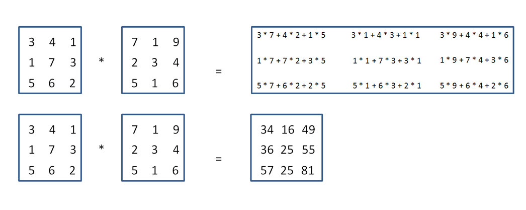
So we have to create a function that can do this kind of multiplication that gets even more complicated in a 4 * 4 matrix.
Note how we create a temporary matrix to hold the result of the calculation. This is due to the fact if the destination and one of the operands is the same pointer there can be unexpected results.
This is another simple transformation. Like the identity function that we defined before, we can achieve scaling by changing the values on the diagonal going from top left to bottom right. The first element will be the scaling on the X axis, the second element will be scaling on the Y axis and the third element will be scaling on the Z axis.
Again not to pollute any transformations applied to the matrix supplied we create a temporary one and multiply both of them together.
Rotation is a little more complicated as it involves some trigonometry. The trigonometry function you want to use depends on which you axis you want to rotate around. Again, these are standard mathematical concepts so feel free to look up this topic in more detail
You could create a function that takes in which vector to rotate around as a parameter. The problem with this is that the maths can be quite advanced. So for this tutorial we will keep all rotations to separate axes.
This function only needs to be called once and the result should be stored in the projection matrix. Unfortunately, it is quite advanced so we won't explain how the functions work technically. We will however explain the parameters that are supplied to it so you will be able to adjust them in the future.
The first parameter that we supply is the matrix that we want to do the projection with. This is like most of the functions we have already described. The second is the Field of View. This is angle that you should be able to see through. 45 Degrees is pretty standard but when you have finished the tutorial feel free to adjust to see the effect. It is the best way to learn.
The next parameter is the aspect ratio. This is usually the width / height of your screen or surface. You wouldn't need this parameter if all screen ratios were the same but unfortunately they are not. This helps the application to look correct on a variety of devices. Which is very important considering the vast array of different devices that are available in the mobile space.
The final two parameters are called zNear and zFar. zNear is how close an object has to be to the camera before it disappears and gets clipped. zFar is the opposite; how far away an object should be from the camera before it is no longer drawn.
This function calls a matrixFrustum function that actually creates the viewing frustum which is what you will see of the scene.
Previously our vertex shader has been really boring and as simple as it could possibly be. However, now we have a lot more interesting things happening.
The first line is just like before; it represents the input vertices. The next line is another input which represents an associated colour for each vertex. This will allow us to make our final object more interesting.
The next line introduces a new concept; a varying. A varying is something that you can use to transfer values across to the fragment shader, as a fragment shader can't take any attributes. The next two lines also introduce a new concept; uniforms. A uniform can be considered to be a little like a global variable. It can be accessed in both the vertex shader and fragment shader but it is read only and can't be edited in either shader. This is the perfect place for the matrices we spoke about above. For this simple example we have combined the model and the view matrices into to the modelView matrix.
In the main function we now set the gl_Position as before but this time instead of just setting it straight to the vertexPosition attribute we multiply the attribute by the projection and the model view matrix before hand. The order in which we do this is important.
The final line in our shader just sets the varying to the attribute we want to use in our fragment shader.
Above is our new fragment shader. This is still very similar to the previous tutorial. This will get more interesting in the tutorials to come, but for now note how we now have the same varying that was in our vertex shader at the top of our fragment shader. We then set the first three elements of glFragColor to it. The fourth one is alpha and as we are not doing any transparency or blending effects we keep this as 1.0 or fully opaque.
Now we have added a few new inputs to our shaders we need to tell the shaders where to get the new information from. This means we need to change our setupGraphics function.
As you can see along with the vertexPosition variable we have a colourPosition, projectionLocation and modelViewLocation. The colourPosition variable uses the exact same function as vertexPosition to link up with the vertexColour in the shader as it is just another attribute. The other two variables use a new function called glGetUniformLocation. This does exactly the same thing as glGetAttribLocation but only for uniforms instead of attributes.
In this case our example is really simple so we won't be changing the projection of the scene at all. For this reason we can just set it up once in the setupGraphics routine. This is the reason we call matrixPerspective here. The parameters should match up to those defined earlier on.
The final change that we have made to this function is that we have enabled GL_DEPTH_TEST. This tells OpenGL ES that distance should be a factor in what things are displayed on the screen. We didn't care about this before because in our previous example we only drew a triangle that is a 2D object with nothing behind it. Now due to the cube being a 3D object, we need to know which faces are in front of each other. OpenGL ES should only draw the fragments for the front face. There are some really good examples online exampling depth testing.
Now we are going to get onto creating the cube. A cube can be thought of as 12 triangles. Each face of the cube being a square of two triangles. This means we need a lot more vertices than in the first example.
Note how we still define everything in the model space. So everything is still done between -1.0 to 1.0. We now have our new Z component which deals with how near or far away a particular vertex is. It makes things much easier to read if you label what vertices refer to what. In most projects the vertices will be generated from a third party tool like Maya or 3D Studio Max.
Next we need to define colours for each of the vertices we have just defined. This is done by defining 3 channels for each vertex. A red channel, a green channel and a blue channel.
Now you will notice it looks like we haven't defined enough vertices or colours to create a cube. If a triangle is made up of 3 vertices and we have 12 triangles we should have 36 vertices shouldn't we? Instead we only have 24. This is because defining 36 vertices takes up a lot of extra space. So we can just define all of the unique points on a face. So that will be one in the top left corner, bottom left corner, bottom right corner and top right corner. We can the pass in a group of indices which map which vertices are involved in which triangles. This saves space as we are using shorts instead of floats.
The drawing scene function has changed quite a bit. We start by clearing the colour and and depth buffers. This hasn't changed but in the previous example we cleared the depth buffer even though it wasn't used. Now it is.
A new part of the early scene rendering is to clear the modelViewMatrix. We set it straight away to the identity function. We then rotate in both the x and y axes by the appropriate angle. The cube and the camera are both still at the origin at this point. If we didn't move the cube we would be inside it as it span around. To avoid that, we move it 10 units into the screen. That way we will be able to see the whole of the spinning cube.
We then do the standard steps of selecting a program to use for our drawing and then we enable both the vertexPosition vertex array and the colourPosition vertex array. We also need to link the projection matrix and the model view matrix up with their counterparts in the shader.
We then can't use the glDrawArrays function because it expects all of the vertices to be defined. As we mentioned before we only defined 24 out of a possible 36. So we need to use a new function called glDrawElements. This function takes in the indices we defined before and draws the triangles that we want for the cube. This is the actual cube drawing function
The final few lines are just to ensure that the cube rotates.
Follow the Getting Started Guide from Building Android samples onwards to build and run the application.
Now move on to adding textures to your cube in Texture Cube or take a look at lighting in Lighting.

