|
CMSIS-View
Record program events, display status information, and analyze execution faults
|

|
|
CMSIS-View
Record program events, display status information, and analyze execution faults
|
|
This section describes how the Event Recorder collects event data, generates time stamps, and transfers this information via a debug unit to a host computer.
The Event Recorder is implemented in the target application using the software component CMSIS-View:Event Recorder which adds the source file EventRecorder.c to the application. Each event is stored in a 16-byte structure that is composed of a 16-bit id, 32-bit time stamp, two 32-bit data values and consistency check values.
To store these events, a circular buffer is provided that can store a minimum of 8 events. The size of this circular buffer is configurable with the #define EVENT_RECORD_COUNT.
The Event Data Recording functions get a parameter id that is composed of level, component number, and message number as shown below:
| id | bits | Description |
|---|---|---|
| message number | 0..7 | identifies the event message information of the software component |
| component number | 8..15 | identifies the software component (also used for filtering, see table below) |
| level | 16..17 | specifies the class of the message for filtering (see table below) |
| — (reserved) | 18..31 | set to 0 |
The level specifies the category of the event message and can be used for filtering:
| level | Message relates to ... |
|---|---|
| EventLevelError = 0 | Run-time error |
| EventLevelAPI = 1 | API function call |
| EventLevelOp = 2 | Internal operation |
| EventLevelDetail = 3 | Additional detailed information of operations |
The component number specifies the software component that the event message belongs to and can be also used for filtering:
| component number | Relation to software components |
|---|---|
| 0x0 .. 0x3F (0 .. 63) | software components of the user application |
| 0x40 .. 0x7F (64 .. 127) | third party middleware components |
| 0x80 .. 0xED (128 .. 237) | MDK-Middleware components |
| 0xEE (238) | Fault component |
| 0xEF (239) | Start/Stop events for Event Statistic information |
| 0xF0 .. 0xFC (240 .. 253) | RTOS kernel |
| 0xFD (253) | Inter-process communication layer (multiprocessor systems) |
| 0xFE (254) | printf-style debug outputs |
| 0xFF (255) | Event Recorder messages |
The following sections describe:
Adding the software component CMSIS-View:Event Recorder to a project will copy the file EventRecorderConf.h into the project that is used to define the configuration parameters of the Event Recorder. It uses Configuration Wizard Annotations, so IDEs that support this can also show a graphical representation of the file:
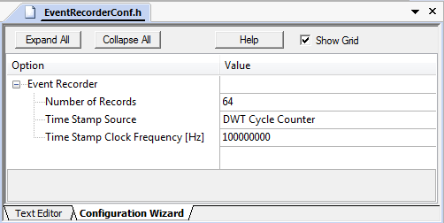
Following configuration parameters are defined in the EventRecorderConf.h file:
| Option | #define | Description |
|---|---|---|
| Number of Records | EVENT_RECORD_COUNT | Specifies the number or records stored in the Event Record Buffer. Each record is 16 bytes. |
| Time Stamp Source | EVENT_TIMESTAMP_SOURCE | Specifies the timer that is used as time base. Refer to Time stamp source below for more information. |
| Time Stamp Clock Frequency [Hz] | EVENT_TIMESTAMP_FREQ | Specifies the initial timer clock frequency. |
Note
- Set the time stamp clock frequency to your target's core clock frequency to avoid problems in determining the correct frequency.
The following time stamp sources can be selected:
| Source | Description |
|---|---|
| DWT Cycle Counter | Default setting. The DWT cycle counter is part of the CoreSight debug interface. DWT is not available with Cortex-M0/M0+/M23. uVision can simulate DWT using a script. |
| SysTick | System tick timer is available on most Cortex-M processors. But in power-down modes it might be disabled. |
| CMSIS-RTOS2 System Timer | The system tick counter provided by a CMSIS-RTOS2 compliant real-time operating system. |
| User Timer (Normal Reset) | User-defined timer that stops by any system reset. Refer to Event Recorder - Timer for more information. |
| User Timer (Power-On Reset) | User-defined timer that stops only by power-on reset. Refer to Event Recorder - Timer for more information. |
Note
- When DWT Cycle Counter is selected on Cortex-M0/M0+/M23, a warning is issued at compile time:
Invalid Time Stamp Source selected in EventRecorderConf.h!- When using the CMSIS-RTOS2 System Timer, it is strongly recommended to set up the Time Stamp Clock Frequency [Hz] (see above) to the correct value to avoid display problems in the Event Recorder and System Analyzer windows.
Arm Cortex-M0/M0+/M23 processors do not offer the DWT Cycle Counter and require therefore alternative time-stamp sources.
SysTick
For applications that do not use the SysTick timer, you may configure EventRecorderConf.h with:
CMSIS-RTOS2 System Timer
For applications that use a CMSIS-RTOS2 compliant RTOS (SysTick timer used by RTOS), you may configure EventRecorderConf.h with:
The DWT Cycle Counter can be simulated with the following debug initialization file, for example Debug_Sim.ini:
Technical data of Event Recorder firmware
Target: Cortex-M3 using DWT cycle counter as timer
| Parameter | ARMCC V6.13.1 | ARMCC V6.13.1 |
|---|---|---|
| Compiler options | -Os | -O3 |
| ROM size | < 1.7k bytes | < 3.4k bytes |
| RAM size @8 records (min) | 292 bytes | 292 bytes |
| RAM size @64 records (default) | 1188 bytes | 1188 bytes |
| EventRecord2 (id+8bytes) | 197 cycles | 184 cycles |
| EventRecord4 (id+16bytes) | 343 cycles | 319 cycles |
| EventRecordData (id+8bytes) | 276 cycles | 252 cycles |
| EventRecordData (id+16bytes) | 425 cycles | 397 cycles |
| EventRecordData (id+24bytes) | 554 cycles | 519 cycles |
| EventRecordData (id+32bytes) | 685 cycles | 643 cycles |
Note
- ROM size is specified for image with all Event Recorder functions being used.
- RAM size can be calculated as
164 + 16 * <Number of Records> (defined by EVENT_RECORD_COUNT in EventRecorderConf.h).- Timing was measured in simulator (zero cycle memory, no interrupts). Function parameter in application is not considered.
Usage of records by Event Recorder functions
| Function | Number of Records used |
|---|---|
| EventRecord2 | 1 |
| EventRecord4 | 2 |
| EventRecordData | (event data length + 7) / 8 |