The BSD server example implement BSD compliant communication on the server side. It shows you how to control the board LEDs on the server via the BSD socket.
BSD sockets are often used for network communication as they provide a well-defined API for exchanging data over the network by utilizing TCP and UDP sockets.
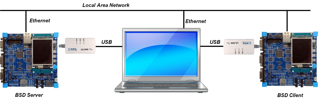
An exemplary setup could look like this:

The BSD Server project are available as part of the Network Reference examples.
Following files implement application-specific logic in the example:
BSD_Server.c contains the application main thread which initializes the Network Component for the BSD server. The server is waiting for a connection from a BSD client.Configuration files for the software components used in the project are located in the ./RTE/ directory and can be modified by users to adjust the operation of related components.
Following configuration files are provided with this example:
./RTE/Network/ folder:Net_Config_BSD.h: BSD Socket configuration.Net_Config_TCP.h: TCP Socket configuration.Net_Config_UDP.h: UDP Socket configuration.Net_Config_ETH_0.h: Ethernet Interface configuration.Net_Config.h: Network Core configuration.Net_Debug.h: Network Debug configuration../RTE/CMSIS/ folder:RTX_Config.h and RTX_Config.c: CMSIS-RTX Configuration files for the RTOS Kernel.When a board layer is added to the project, corresponding configuration files for the board and device components will become available in the local ./Board/ directory.
In order to build the project it shall be extended with a compatible board layer that provides following interfaces as connections:
CMSIS_ETH: CMSIS-Driver for Ethernet interfaceCMSIS_VIO: CMSIS-Driver for Virtual I/O interfaceSTDOUT: Standard Output redirectionWorking with MDK-Middleware Examples explains the workflow for accessing, configuring and building an MDK-Middleware example project for your target hardware.
Hardware Setup
Board-specific hardware setup such as jumpers, Ethernet ports, power supply, etc. is documented in the board layer description (README.md) of your selected target.
Example execution
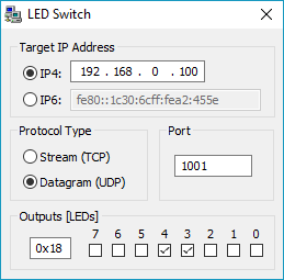
To test the BSD Server example stand-alone, run the Windows application LEDSwitch.exe that is available as part of Keil MDK uVision and is located in <install_dir>\ARM\Utilities\LEDSWitch\Release\ folder, where <install_dir> refers to the Keil MDK uVision installation directory. The program runs stand-alone without installation.
Type in the IP address of your development board (IPv4 and IPv6 addresses are accepted). When connected, you can control the on-board LEDs.
Notes:
- The BSD Server uses static IP address defined in
Net_Config_ETH_0.hfile. By default it is#define ETH0_IP4_ADDR "192.168.0.100". You would need to change this IP address if your LAN setup operates with different IP addresses.- The default port is defined in the
BSD_Server.cfile as#define SOCK_PORT 1001.
