Theory of Operation
The SDS Framework enables to record and playback one or more data streams to an application that is under development as shown in the diagram below. With the SDSIO Interface the data streams are connected to SDS data files. The file storage can be either embedded within the system and accessed by a file system or external on a host computer and accessed by a communication interface such as Ethernet or USB.
The DSP or ML algorithms that are tested operate on blocks and are executed periodically. This documentation uses these terms:
- Data Block: is a set of input or output data which is processed in one step by a DSP or ML compute note.
- Block size: is the number of bytes of a data block.
- Interval: is the periodic time interval at which the compute node executes.
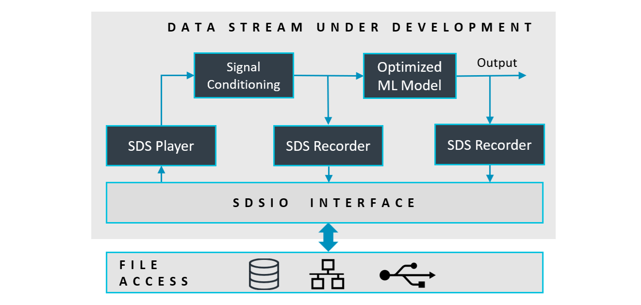
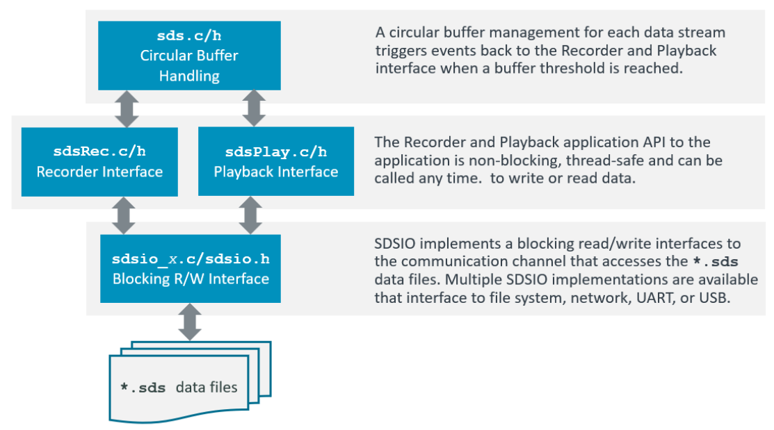
The core of the SDS-Framework is a circular buffer handling (sds_buffer.c/h) that is controlled by the Recorder/Player interface functions (sds_rec_play.c/h). This circular buffer is the queue for the file I/O communication (sdsio_x.c / sdsio.h). Using the Recorder/Player functions, the data stream under development may read and write data streams as shown in the diagram above.
Usage
The following diagram shows the usage of the SDS Recorder and Player functions (executed in sdsRecPlayThread). The sdsControlThread controls the overall execution. AlgorithmThread is the thread that executes Signal Conditioning (SC) and ML Model.
SDS Data Files
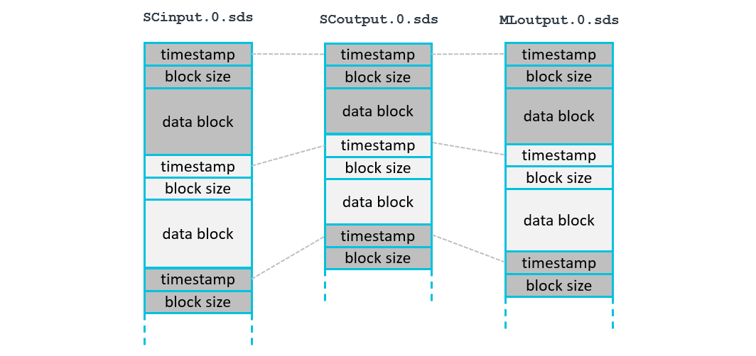
Each data stream is stored in a separate SDS data file. In the diagram below SCinput.0.sds is the input to Signal Conditioning, SCoutput.0.sds is the output of Signal Conditioning, and MLoutput.0.sds is the output of the ML Model. Each execution of the algorithm is represented in a data block with a timestamp. The timestamp allows to correlate the blocks of different streams. In the above example, all blocks of one algorithm execution have the same timestamp value.
- Each call to the function
sdsRecWritewrites one data block. - Each call to the function
sdsPlayReadreads one data block.
Filenames
SDS data files use the naming format <name>.<file-index>.sds. <name> is the base name specified by the user, and <file-index> is a sequential number that starts at 0.
Recording (sdsRecOpen):
The sdsRecOpen function takes <name> as input. When connected to a file system (e.g., the SDSIO-Server), it scans for existing files with names matching the pattern <name>.<file-index>.sds, starting at index 0. It uses the first available index that does not yet exist to create a new file for recording.
Example:
If files SensorX.0.sds through SensorX.10.sds exist, the next file created will be SensorX.11.sds.
Playback (sdsPlayOpen):
The sdsPlayOpen function also takes <name> as input and determines which file to play based on the contents of a corresponding index file, <name>.index.txt. The following procedure outlines how sdsPlayOpen determines the playback file:
- The function checks if
<name>.index.txtexists and contains a valid number.- If it exists and contains a valid index (e.g., 3), that number is used as the
<file-index>. - If the file does not exist or contains an invalid value, the index defaults to
0.
- If it exists and contains a valid index (e.g., 3), that number is used as the
- The file
<name>.<file-index>.sdsis then opened for playback.- If the file exists, it is opened for playback. The index file
<name>.index.txtis updated to<file-index> + 1for the next call to sdsPlayOpen. - If the file does not exist, playback fails and the index file is created or reset to 0.
- If the file exists, it is opened for playback. The index file
This mechanism enables automatic sequential playback, while still allowing the user to select the initial playback index by editing the index file.
Example:
If SensorX.index.txt contains the value 2, the sdsPlayOpen function will attempt to open the file SensorX.2.sds.
- If the file exists, it is played and the index file is updated to 3 for the next playback.
- If the file does not exist, playback fails and the index file is reset to 0.
Timestamp
The timestamp is a 32-bit unsigned value and is used for:
- Alignment of different data streams that have the same timestamp value.
- Order of the SDS data files captured during execution.
- Combining multiple SDS file records with the same timestamp value.
The same timestamp connects different SDS file records. It is therefore useful to use the same timestamp for the recording of one iteration of a DSP or ML algorithm. In most cases the granularity of an RTOS tick (typically 1ms) is a good choice for a timestamp resolution.
File Format
The SDS Framework uses a binary data file format to store the individual data streams. It supports the recording and playback of multiple data streams that may have jitters. Therefore each stream contains timestamp information that allows to correlate the data streams as it is for example required in a sensor fusion application.
The binary data format (stored in *.<n>.sds data files) has a record structure with a variable size. Each record has the following format:
- timestamp: record timestamp in tick-frequency (32-bit unsigned integer, little endian)
- data size: number of data bytes in the record (32-bit unsigned integer, little endian)
- binary data: SDS stream (little endian, no padding) as described with the
*.sds.ymlfile.
YAML Metadata Format
The content of each data stream may be described in a YAML metadata file that is created by the user. The following section defines the YAML format of this metadata file. The file sds.schema.json is a schema description of the SDS Format Description.
sds: |
Start of the SDS Format Description |
|---|---|
name: |
Name of the Synchronous Data Stream (SDS) |
description: |
Additional descriptive text (optional) |
frequency: |
Capture frequency of the SDS |
tick-frequency: |
Tick frequency of the timestamp value (optional); default: 1000 for 1 millisecond interval |
content: |
List of values captured (see below) |
content: |
List of values captured (in the order of the data file) |
|---|---|
- value: |
Name of the value |
type: |
Data type of the value |
offset: |
Offset of the value (optional); default: 0 |
scale: |
Scale factor of the value (optional); default: 1.0 |
unit: |
Physical unit of the value (optional); default: no units |
Example
This example defines a data stream with the name "sensorX" that contains the values of a gyroscope, temperature sensor, and additional raw data (that are not further described).
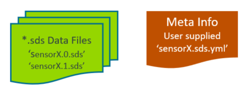
The binary data that are coming form these sensors are stored in data files with the following file format: <sensor-name>.<file-index>.sds. In this example the files names could be:
   sensorX.0.sds   # capture 0
   sensorX.1.sds   # capture 1
The following sensorX.sds.yml provides the format description of the SDS sensorX binary data files and may be used by data conversion utilities and data viewers.
sds:                   # describes a synchronous data stream
  name: sensorX        # user defined name
  description: Gyroscope stream with 1KHz, plus additional user data
  frequency: 1000
  content:
  - value: x           # Value name is 'x'
    type:  uint16_t    # stored using a 16-bit unsigned int
    scale: 0.2         # value is scaled by 0.2
    unit: dps          # base unit of the value
  - value: y
    type: uint16_t
    scale: 0.2
    unit: dps
  - value: z
    type: uint16_t
    unit: dps          # scale 1.0 is default
  - value: temp
    type: float
    unit: degree Celsius
  - value: raw
    type: uint16_t     # raw data, no scale or unit given
  - value: flag
    type: uint32_t:1   # a single bit stored in a 32-bit int
Code Example
The following code snippets show the usage of the Recorder Interface. In this case an accelerometer data stream is recorded.
#include "sds_rec_play.h"

// variable definitions
struct {                          // sensor data stream format
  uint16_t x;
  uint16_t y;
  uint16_t z;
} accelerometer [30];             // number of samples in one data stream record

sdsRecPlayId_t *accel_id;         // data stream id
uint8_t accel_buf[(sizeof(accelerometer)*2)+0x800];      // data stream buffer for circular buffer handling
int32_t n;                        // number of bytes written to data stream
     :
// *** function calls ***
   sdsRecPlayInit(NULL);          // init SDS Recorder/Player
     :
   // open data stream for recording
   accel_id = sdsRecOpen("Accel", accel_buf, sizeof(accel_buf));
     :
   // write data in accelerometer buffer with timestamp from RTOS kernel.
   timestamp = osKernelGetTickCount();
   n = sdsRecWrite(accel_id, timestamp, accelerometer, sizeof(accelerometer));
   if (n != sizeof(accelerometer)) {
     ... // unexpected size returned, error handling
   }
     :
  sdsRecClose (accel_id);         // close data stream
Buffer Size
The size of the data stream buffer depends on several factors such as:
- the communication interface technology that may impose specific buffer size requirements to maximize data transfer rates.
- the frequency of the algorithm execution. Fast execution speeds may require a larger buffer.
As a guideline, the buffer size should be at least (2 × block size) + 2 KB.
The minimum recommended buffer size is 0x1000 (4 KB).
SDSIO Server Protocol
The SDSIO Server uses a simple protocol for data exchange between a Host computer and the embedded target that integrates an SDSIO Interface. The protocol assumes that the correct communication to the server is already ensured by the underlying technology (TCP/IP or USB) and therefore no extra check is implemented.
The following conventions describe the command semantic used in the following documentation:
| Symbol | Description |
|---|---|
| > | Prefix indicating the direction: Command from target to Host. |
| < | Prefix indicating the direction: Response from Host to target. |
| WORD | 32-bit value (low byte first). |
| **** | The field above has exactly one occurrence. |
| ++++ | The field above has a variable length. |
Commands:
Commands are sent from the embedded target to the Host computer running the SDSIO Server.
| ID | Name | Description |
|---|---|---|
| 1 | SDSIO_CMD_OPEN | Open an SDS data file |
| 2 | SDSIO_CMD_CLOSE | Close an SDS data file |
| 3 | SDSIO_CMD_WRITE | Write to an SDS data file |
| 4 | SDSIO_CMD_READ | Read from an SDS data file |
| 5 | SDSIO_CMD_PING | Ping Server |
Each Command starts with a Header (4 Words) and optional data with variable length. Depending on the Command, the SDSIO Server replies with a Response that repeats the Header and delivers additional data.
SDSIO_CMD_OPEN
The Command ID=1 SDSIO_CMD_OPEN opens an SDS data file on the Host computer. Mode defines read (value=0) or write (value=1) operation. Len of Name is the size of the string in bytes.
SDS data filenames use the following file format: <name>.<file-index>.sds, where Name is the base file name of the SDS data file and <file-index> is a sequential number maintained by SDSIO Server (for details see section Filenames).
| WORD |  WORD  | WORD | WORD *******|++++++|
>  1   |   0    | Mode | Len of Name | Name |
|******|********|******|*************|++++++|
The Response ID=1 SDSIO_CMD_OPEN provides a Handle that is used to identify the file in subsequent commands.
| WORD |  WORD  | WORD | WORD *******|
<  1   | Handle | Mode | 0           |
|******|********|******|*************|
SDSIO_CMD_CLOSE
The Command ID=2 SDSIO_CMD_CLOSE closes an SDS data file on the Host computer. The Handle is the identifier obtained with SDSIO_CMD_OPEN. There is no Response from the SDSIO Server on this command.
| WORD |  WORD  | WORD | WORD |
>  2   | Handle |  0   |  0   |
|******|********|******|******|
SDSIO_CMD_WRITE
The Command ID=3 SDSIO_CMD_WRITE writes data to an SDS data file on the Host computer. The Handle is the identifier obtained with SDSIO_CMD_OPEN. Size is the Data size in bytes. There is no Response from the SDSIO Server on this command.
| WORD |  WORD  | WORD | WORD |++++++|
>  3   | Handle |  0   | Size | Data |
|******|********|******|******|++++++|
SDSIO_CMD_READ
The Command ID=4 SDSIO_CMD_READ reads data from an SDS data file on the Host computer. The Handle is the identifier obtained with SDSIO_CMD_OPEN. Size are the number of bytes that should be read.
| WORD |  WORD  | WORD | WORD |
>  4   | Handle | Size |  0   |
|******|********|******|******|
The Response ID=4 SDSIO_CMD_READ provides the data read from an SDS data file on the Host computer.
Size is the Data size in bytes that was read and Status with nonzero = end of stream, else 0.
| WORD |  WORD  |  WORD  | WORD |++++++|
<  4   | Handle | Status | Size | Data |
|******|********|********|******|++++++|
SDSIO_CMD_PING
The Command ID=5 SDSIO_CMD_PING verifies if the Server is active and reachable on the Host.
| WORD | WORD | WORD | WORD |
>  5   |  0   |  0   |  0   |
|******|******|******|******|
The Response ID=5 SDSIO_CMD_PING returns the Status with nonzero = server active, else 0
| WORD | WORD |  WORD  | WORD |
<  5   |  0   | Status |  0   |
|******|******|********|******|
SDSIO Message Sequence
This is the message sequence of the SDS DataTest example using SDSIO Server. It contains the following threads that execute on the target.
- Control: Overall execution Control thread (sdsControlThread)
- Algorithm: Algorithm under test thread (AlgorithmThread)
- Recorder/Playback: SDS Recorder/Playback thread (sdsRecPlayThread)
The Server is the SDSIO Server executing on the target system.
Recording flowchart
Playback flowchart