Mobile devices
Mobile devices are compact, battery-powered systems that rely on passive cooling. They are built around a System on a Chip ( SoC ) that incorporates the processing and memory elements of the computer at the heart of the device.
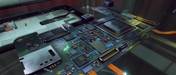
Mobile device form factor
Mobile systems are built for energy efficiency, designed to give high performance without excessive battery drain or overheating. Despite this focus on efficiency, a high-end device can generate more heat than it can dissipate under a sustained heavy workload. Every watt of power needed to drive the electronics will be turned into heat that needs to be dissipated. An application can make heavy use of the CPU, GPU, or memory bandwidth, but cannot usually sustain heavy simultaneous use of all of them for long periods.
Mains-powered graphics systems, such as desktop PCs and game consoles, are actively cooled with large heat sinks and fans. This allows them to sustain maximum performance across all components, all of the time. This simplifies optimization because it allows you to treat each component individually, and you only need to worry about improving performance bottlenecks on the critical path.
Conversely, optimization for a mobile system must be a holistic activity. CPU, GPU, and memory bandwidth are all competing for the same power budget, so you must consider them all together. Reducing load in any part of a thermally constrained system helps, even if it is not on the critical path.
Mobile SoCs
Mobile devices are built around a SoC, which integrates a logic die and a DRAM die. The logic die houses the processors such as the CPU and GPU. The DRAM die provides the system memory.
To optimize a system holistically, you need to understand its components. Let us look at the major components inside the logic die that are used to implement a graphical application.


CPUs
The CPUs in the SoC run application software, the graphics driver, and the host operating system.
Mobile SoCs are usually heterogeneous multi-core systems, containing multiple CPU types with different performance-efficiency trade-offs.
- High-performance “big” cores deliver the best single-thread performance. They are also the least efficient in terms of energy per operation, and the most expensive in terms of silicon area.
- More efficient “mid” cores offer lower peak performance, but have better energy efficiency and are normally more numerous.
- Small “little” cores further reduce peak performance to improve energy efficiency and reduce silicon area.
Note
In the latest silicon process nodes there is little energy efficiency difference between a “little” core and a “mid” core running at its most efficient clock frequency. Contemporary high-performance designs therefore commonly include only “big” and “mid” cores.
The operating system scheduler is aware of these differences, and will assign threads to the most appropriate CPU to balance performance and energy efficiency based on processing load.
GPUs
The GPU in the SoC runs the graphical rendering workloads, as well as general-purpose GPU ( GPGPU ) compute workloads. Work is submitted to the GPU via a high-level API — such as OpenGL ES, Vulkan, or OpenCL — and prepared by the graphics driver software running on the CPU.
GPU workloads are highly parallelizable. Performance can be scaled up by making an efficient shader core and then increasing the number of shader cores and the available memory bandwidth. GPU designs are therefore homogeneous, with no equivalent of the heterogeneous mix of CPU core types.
DPUs
The Display Processing Unit ( DPU ) in the SoC handles the composition required to create a displayable frame, and outputs the resulting image to the display hardware. The composition work can involve scaling, rotation, and color conversion of individual layers, as well as blending multiple layers together.
DPUs operate under strict real-time requirements to ensure that they meet display refresh timing deadlines. If composition is too complex for the DPU to handle, the display subsystem will fall back to using the GPU to create the displayable frame. Applications should avoid graphics API usage patterns that trigger the GPU composition fallback, because it increases the cost of producing a frame.
Memory system
The memory system in the SoC provides the interconnects that move data around the system. It also provides the caches and external DRAM that store it.
CPUs and the GPU each have a local cache hierarchy for storing data close to the processor using it. This increases performance and reduces power consumption, provided the data is in the cache when accessed.
Mobile SoCs increasingly include a large shared System-Level Cache ( SLC ), which sits between the processors and the external DRAM. The system cache reduces external memory bandwidth, which is particularly beneficial for thermally constrained mobile devices because accessing off-chip DRAM is energy intensive.
DRAM
Off-chip DRAM provides the bulk storage for all of the running programs and their data. DRAM uses a different manufacturing process to CMOS logic, and so must be implemented on a separate silicon die. Driving the signals from the logic die to the DRAM die is energy intensive. A byte of DRAM access is orders of magnitude more expensive than a byte returned from a local on-chip cache.
Optimizing your application for DRAM access efficiency is so important that an entire section is dedicated to explaining the reasons why in more detail.
Thermal management
A SoC without thermal management could become dangerously hot, potentially burning the user holding the device or damaging the electronics. To prevent this, devices implement active thermal management, managing clock frequency assignments to lower power draw when thermal limits are approached or exceeded.
Mobile thermal management ten years ago was simplistic. It was often as basic as limiting the maximum clock frequencies after a temperature threshold was breached, and holding that limit until the device had sufficiently cooled. The problem with this approach was that, as soon as the limit was released, the workload quickly overheated the device again. The resulting user experience was poor, with severe and prolonged periods of performance stuttering that would remain until the workload complexity dropped.


Modern mobile thermal management is much more sophisticated. It uses thermal sensors to track the current temperature, and power models to predict how changes in clock frequency will impact power consumption. Clock frequency only increases when it is expected to stay within sustainable thermal limits. Any required throttling can also focus on the component that is using the most power. This results in a much smoother user experience, where the sustained performance converges on the thermally sustainable performance for the device without overshooting. While peak performance will be lower than the older method, it is far more consistent and avoids the disruptive stuttering.


Mobile devices are increasingly adopting advanced cooling solutions, such as flattened heat pipes and vapor chambers, to transfer heat away from the SoC more effectively. Improved cooling enables the SoC to sustain higher performance, because it can consume more power before hitting its thermal limits.
However, mobile devices will always face constraints imposed by user comfort. Users are in direct contact with the device chassis that we are using as a heat sink. As a result, thermal design is ultimately limited by how warm the device can become before it feels uncomfortable to hold. Few users want to play games with hot, sweaty hands.


Frequency management
In addition to its use in thermal management, frequency control is also an essential mechanism for optimizing the energy efficiency of running workloads.
Operating a processor pipeline stage at a given clock frequency requires sufficient supply voltage to ensure the electrical signals propagate through it within one clock period. Increasing clock frequency requires a higher voltage to make the signals propagate faster.
The energy required to toggle the transistors in a circuit is proportional to the voltage squared. As a result, increasing clock frequency reduces energy efficiency.
Mobile systems use Dynamic Voltage and Frequency Scaling ( DVFS ) to constantly adjust their performance. The goal is to minimize voltage to maximize energy efficiency while still running at a frequency that can meet the workload performance requirements.
Note
Frequency changes make profiling using time as the primary metric very challenging. See the What is performance section for more details.