 |
OpenGL ES SDK for Android
ARM Developer Center
|
|
OpenGL ES SDK for Android
ARM Developer Center
|
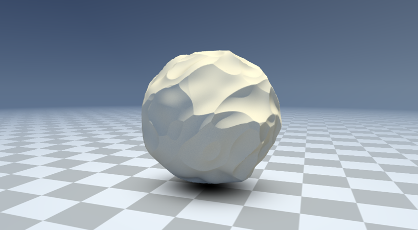
This sample uses OpenGL ES 3.1 and the Android extension pack to perform displacement mapping with tessellation. The sample investigates common techniques used to improve performance and visuals.
The Android extension pack adds many new features to mobile, that have until now been exclusive to desktop OpenGL. New pipeline stages, such as geometry and tessellation shaders, are now available to the programmer. This sample showcases the use of tessellation on a Mali GPU.
In the sample we apply a displacement map to a coarse mesh, to generate detailed geometry on the fly. We combine this with a screen-space based LOD computation to progressively vary the level of detail, depending on how much screen area the geometry covers.
Tessellation introduces three optional pipeline stages - two of them programmable - located conveniently after the vertex shader and before the fragment shader. These stages are capable of generating additional geometry. How many triangles, or where the generated geometry should be placed, is programmable in the Tessellation Control and Tessellation Evaluation shaders. These both operate on a per-vertex basis, and can see all the vertices of a single primitive.
The ability to generate additional geometry gives increased expressive power to the programmer. However, the ease of use is debatable. Realtime tessellation is notorious for requiring great care to avoid performance issues, patch gaps, mesh swimming or other visual artifacts. In this sample we will take a look at one particular usage of tessellation, as well as some tricks that can be applied to improve performance and hide artifacts. Before moving on, we briefly mention some common use cases, some of which we leave to the reader for further investigation:
For further reading, we refer to 10 fun things to do with tessellation [4], describing more uses such as terrain or hair rendering. For more information about the basics of tessellation, these articles ([5], [6]) provide a concise introduction.
In this sample we apply a displacement map to a spherical mesh, producing cool planetoidal-esque shapes. We begin by procedurally generating a cube mesh, where each face is predivided into a number of quadrilateral patches. A patch is a new primitive type, and defines the points that can be operated on in the tessellation shaders. These patches are further subdivided - into proper triangles - with a level of detail dictated by the control shader. As shown in the figure, we can produce a sphere from the tessellated mesh by normalizing each vertex to unit length.
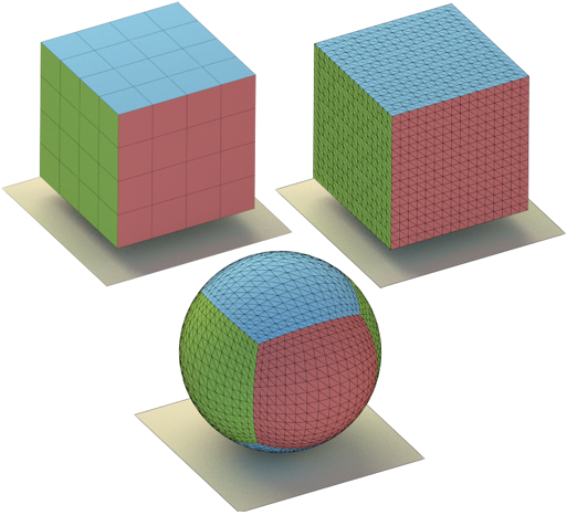
cube will be denser near the seams of the faces on the sphere."
The displacement map is generated using the popular 3D modelling package Blender, by the use of combining procedural textures of different types. To apply the map to the sphere, we need a mapping between vertex coordinates on the sphere and texel coordinates in the texture. Several methods for mapping a sphere exist, each with their own advantages and drawbacks. We chose a cubemap, where each side of the initial cube is mapped to one square in a texture of six.
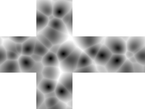
Sampling the cubemap is done by intersecting the sphere normal with the associated cube face. The mathematics for this turn out to be very simple, making cubemaps one of the more efficient mappings. Cubemap texture sampling is available as a hardware-level operation in the shaders.
Care should be taken to avoid visible seams between cubemap faces. Seamless filtering is available as a texture parameter hint in OpenGL, and may avoid issues. Further improvements can be made by averaging edges in the texture beforehand.
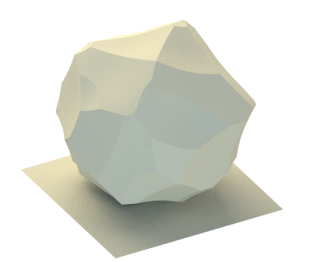
In the evaluation shader, we renormalize the generated vertices and sample the texture using the sphere normal (parallel to the vertex position in our case!). The vertex is finally displaced by an amount proportional to the color of the texel.
While the basics of the displacement mapping technique are apparently simple, a good result does not come along by itself. In the next sections we describe some pitfalls associated with tessellation, as well as some optimizations that can be made to improve performance and visuals.
The tessellation evaluation shader will be run for each vertex generated by the tessellator. However, many of these vertices might end up being invisible when finally rendered to the screen. It is therefore beneficial to determine whether or not we can cull a patch, before submitting it to the tessellator, where further work would be wasted.
We can cull a patch by setting its tessellation factors to zero, effectively generating no additional geometry. This is done in the control shader, by checking whether all the vertices of a patch are either offscreen or are hidden by front geometry. In the case of a perfect sphere, a patch is hidden if all of its normals are facing away from the camera in view-space. That is, the z-component of each normal is negative. However, when the sphere is morphed we may have geometry that is displaced far enough to be visible from behind the sphere. A straightforward fix is to require that the z-component is less than some handpicked bias.
Finally, we project the patch vertices to normalized device coordinates, and compare the vertices with the frustum bounds to determine if the patch is fully offscreen.
Patches that do not cover a large screen area need not be tessellated too much. We take advantage of this to increase performance. The method used in the sample is a naive implementation of screen-space coverage adaptive tessellation, and works as follows:
Care must be taken to ensure that the edge levels are computed consistently across all patches. If two neighbouring edges do not have the same tessellation level, horrible gaps or flickering may occur.
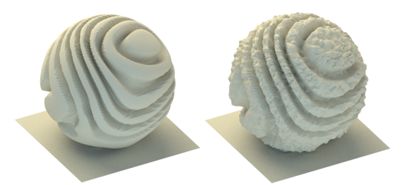
Tessellation of meshes has close ties with sampling theory. I.e. the generated geometry must have a high enough sampling rate, in order to reconstruct the geometry described by the displacement map. If the sampling rate is too low, we could attempt to reduce the frequency of the displacement map to compensate.
In the sample code, we attempt to do this by selecting a lower quality mipmap of the texture, depending on the tessellation. Mipmaps are pre-calculated, optimized versions of the original texture, each of which downscaled by a factor of two from the previous level. You can think of this as reducing the frequency of the displacement geometry by a half, for each mipmap level.
A clever strategy could be to actually analyze the frequency components of the map, and select an appropriate mipmap level based on the tessellation level. In the sample we simply linearly select between some lower-bounded mipmap and the best mipmap based on camera distance.
It is possible that the displacement map simply has too much detail, than can be represented by the tessellated mesh. The result of this is aliasing, and can be painfully visible.
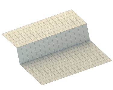
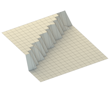
The following figures demonstrate the phenomenom. In both cases, the displacement map consisted of a single sharp line, dividing the map into a black and white section. In the first figure, the line was aligned with the grid, but slightly offset from the sampling center. In the second figure, the line was not aligned with the grid.
This jarring effect can be somewhat reduced by simply increasing the global tessellation factor, but that approach is not scaleable. Several techniques have been developed for preventing aliasing in tessellation. Such a technique must prevent gaps between patches and mesh swimming (vertices that squirm around when the level of detail is varied by the camera distance). We mention some ideas:
If your mesh consists of large flat areas - such as the world's greatest virtual concrete slab [1] - we can reduce the triangle count with no apparent loss of fidelity. Geometry adaptive tessellation does this by examining the curvature or the underlying surface, and varies the level of tessellation accordingly. A possible approach applied to subdivision surfaces is described in [8].
Hopefully, this sample has demonstrated the potential use cases of GPU accelerated tessellation, as well as what pitfalls that lay before the eager programmer. If the reader decides to go further with tessellation, it is important to consider that the Mali GPU - in its own peculiarity - does not have a dedicated tessellation unit. The performance of tessellation can be highly dependent on the underlying hardware, and should be used with care.
[1] The Tech Report. "The world's greatest virtual concrete slab", available online.
[2] Loop, Schaefer. "Approximating Catmull-Clark Subdivision Surfaces with Bicubic Patches", available online.
[3] Lee, et al.. "Displaced Subdivision Surfaces", available online.
[4] Castaño, Ignacio. "10 Fun Things to do with Tessellation", available online.
[5] The Little Grasshopper. "Triangle Tessellation with OpenGL 4.0", available online.
[6] OpenGL SuperBible. "Primitive Processing in OpenGL", available online.
[7] Rákos, Daniel. "History of hardware tessellation", available online.
[8] GPU Gems 2. "Adaptive Tessellation of Subdivision Surfaces with Displacement Mapping", available online.

