|
CMSIS-Driver Implementations
MCU independent CMSIS-Driver implementations
|

|
|
CMSIS-Driver Implementations
MCU independent CMSIS-Driver implementations
|
|
The Shield layer adds support for additional hardware via plugin shields.
The Pack Content provides implementations of Shield layers for the following Arduino Uno WiFi shields:
| Shield layer | Description |
|---|---|
| Inventek_ISMART43362-E | Shield layer for Inventek ISMART43362-E WiFi Shield. |
| Sparkfun_DA16200 | Shield layer for Sparkfun DA16200WiFi Shield. |
| Sparkfun_ESP8266 | Shield layer for Sparkfun ESP8266 WiFi Shield. |
| WizNet_WizFi360-EVB | Shield layer for WizNet WizFi360-EVB WiFi Shield. |
Shield layer for Inventek ISMART43362-E Arduino Uno WiFi Shield. The shield is connected via an Arduino header using an SPI interface.
| Provided API Interface | Description |
|---|---|
| CMSIS_WIFI | CMSIS-Driver WIFI (instance 0) |
| Consumed API Interface | Description |
|---|---|
| ARDUINO_UNO_SPI | CMSIS-Driver SPI connected to Arduino SPI pins D11..D13 |
| ARDUINO_UNO_D9,D10 | CMSIS-Driver GPIO connected to Arduino digital I/O pins D9,D10 |
| CMSIS-RTOS2 | CMSIS-RTOS2 compliant RTOS |
The ISMART43362-E Shield has two options to communicate with the underlying target hardware: UART and SPI.
By default, the module is flashed with the firmware for UART communication.
To enable SPI communication, follow these steps to flash the module:
Prepare the hardware
Prepare the software

In the es-WiFi Demo application, execute:


After the firmware is updated, the console will show the message "Resetting...":

You can now disconnect the module from the PC as it contains the new SPI firmware.
If you want to flash a different firmware later, please visit Inventek's Firmware page for the latest binary files.
Note: Firmware version ISM43362_M3G_L44_SPI_C6.2.1.8 is not supported!
Shield layer for Sparkfun DA16200 Arduino Uno WiFi Shield. The shield is connected via an Arduino header using an UART interface.
| Provided API Interface | Description |
|---|---|
| CMSIS_WIFI | CMSIS-Driver WIFI (instance 0) |
| Consumed API Interface | Description |
|---|---|
| ARDUINO_UNO_UART | CMSIS-Driver USART connected to Arduino UART pins D0..D1 |
| CMSIS-RTOS2 | CMSIS-RTOS2 compliant RTOS |
Shield layer for Sparkfun ESP8266 Arduino Uno WiFi Shield. The shield is connected via an Arduino header using an UART interface.
| Provided API Interface | Description |
|---|---|
| CMSIS_WIFI | CMSIS-Driver WIFI (instance 0) |
| Consumed API Interface | Description |
|---|---|
| ARDUINO_UNO_UART | CMSIS-Driver USART connected to Arduino UART pins D0..D1 |
| CMSIS-RTOS2 | CMSIS-RTOS2 compliant RTOS |
For correct operation of the Sparkfun ESP8266 WiFi Shield using the Arduino R3 header, make sure that the jumpers are fitted as described in the table below:
| Jumper | Setting |
|---|---|
| J26 | closed |
| J27 | 1-2 |
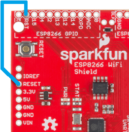
For correct operation, the Sparkfun ESP8266 WiFi Shield requires a proper reset functionality ensured by connecting together the RESET pin on the Arduino connector with the RST pin in the area marked as ESP8266 GPIO, see the picture below:
For stable operation, make sure that you are using an external DC 5V power supply (connected to J2).
Also, fit a jumper J1 to 1-2 closed and set the switch SW1 to position 2-3.
Shield layer for WizNet WizFi360-EVB Arduino Uno WiFi Shield. The shield is connected via an Arduino header using an UART interface.
| Provided API Interface | Description |
|---|---|
| CMSIS_WIFI | CMSIS-Driver WIFI (instance 0) |
| Consumed API Interface | Description |
|---|---|
| ARDUINO_UNO_UART | CMSIS-Driver USART connected to Arduino UART pins D0..D1 |
| CMSIS-RTOS2 | CMSIS-RTOS2 compliant RTOS |
The latest firmware images are available on the GitHub: https://github.com/wizfi/Release.
Instructions on how to flash the firmware onto the device can be found on the WIZnet Documents page: https://docs.wiznet.io/Product/Wi-Fi-Module/WizFi360/documents#firmware-update-guide.