The SPI Server application provides features used by the CMSIS-Driver Validation suite to test physical operation of the SPI driver.
It is available for the STMicroelectronics STM32F429I-DISC1 board and as a template for any board with available Board Layer and configured CMSIS compliant SPI driver.
- Note
- STM32F429I-DISC1 was selected because its SPI driver is stable and supports all required features.
-
For running on STM32F429I-DISC1 board, see Running on STM32F429I-DISC1 board.
-
For running on other hardware, see Running on specific hardware.
Features
- Read version information
- Read capabilities information (auto-detected)
- Set and read buffer contents
- Read last transfer count
- Execute transfer in Slave or Master mode
Operation
The Server waits for a command from the SPI Client (Driver Validation), executes it, and then waits for the next one. Most commands have no additional data phase, though some do. The Server operates as an SPI Slave except when a Master transfer is explicitly requested; after completing it, the Server returns to Slave mode.
Configuration
Communication settings are defined in SPI_Server_Config.h file.
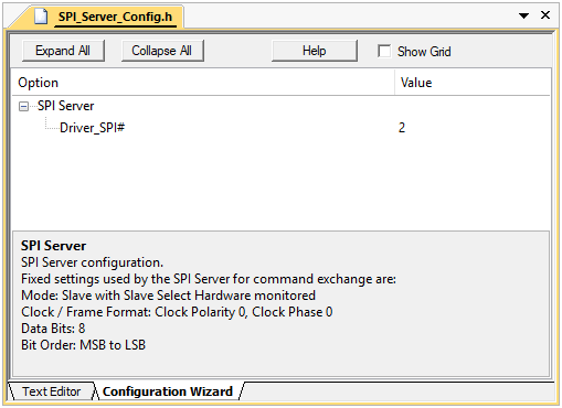
SPI_Server_Config.h configuration file in Configuration Wizard view mode
Configuration settings
- Driver_SPI# - selects the driver instance used by the Server.
- Communication settings (fixed for command exchange):
- Mode: Slave with hardware-monitored Slave Select
- Clock/Frame: Clock Polarity 0/ Clock Phase 0
- Data Bits: 8
- Bit Order: MSB to LSB
- Note
- The SPI Server receives commands as an SPI Slave using the Slave Select line. The Server's SPI driver must support hardware-monitored Slave Select functionality.
Commands
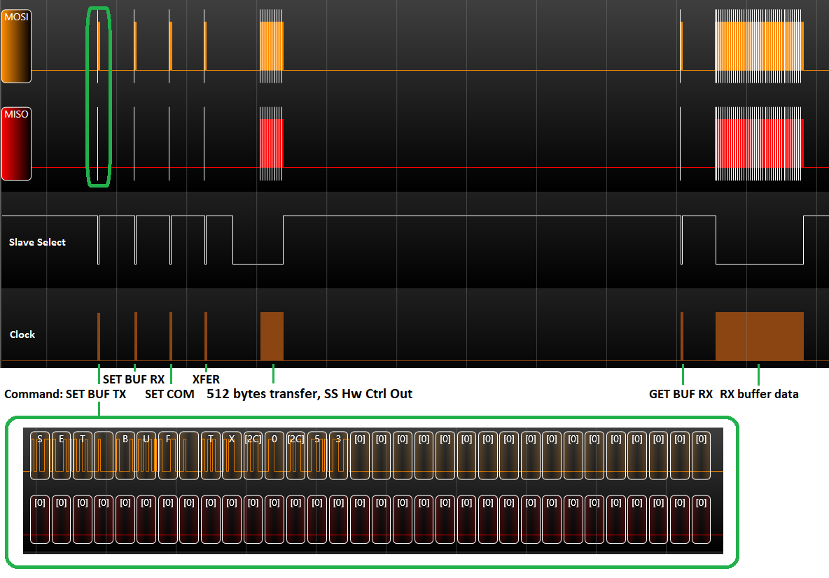
Commands are human-readable (ASCII) for simpler analysis with an SPI bus analyzer.
- GET VER - get Server version
- GET CAP - get capabilities (auto-detected)
- SET BUF - initialize Rx/Tx buffer content
- GET BUF - retrieve Rx/Tx buffer content
- SET COM - specify transfer configuration for the next XFER
- XFER - trigger a transfer
- GET CNT - retrieve number of transferred items in the last transfer
- Note
- For detailed command descriptions, see README.md in project root.
Example capture (Master transfer validation):
Running on STM32F429I-DISC1 board
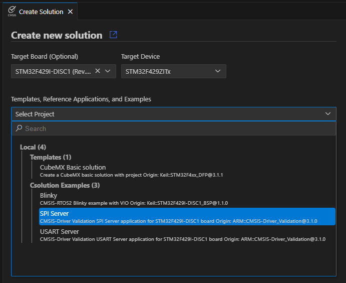
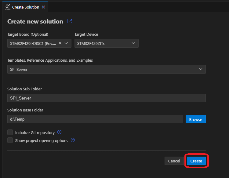
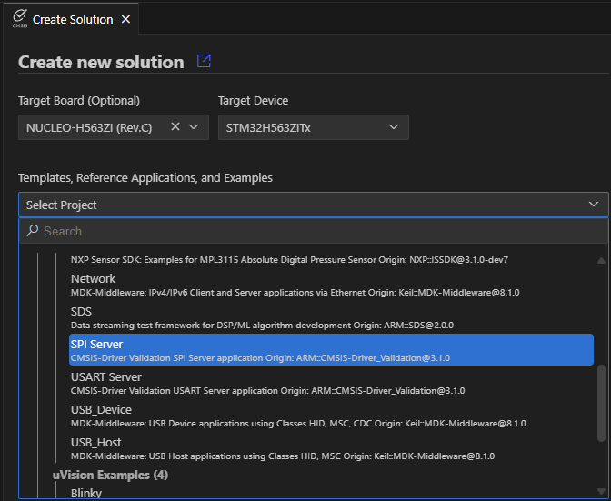
Using the Arm CMSIS Solution VS Code extension, create a new solution from example:
- In the CMSIS extension, click Create a New Solution.
- Select an STM32F429I-DISC1 board as a Target Board.
- Under Templates, Reference Applications, and Examples, select SPI Server (CMSIS-Driver Validation SPI Server application for STM32F429I-DISC1 board).
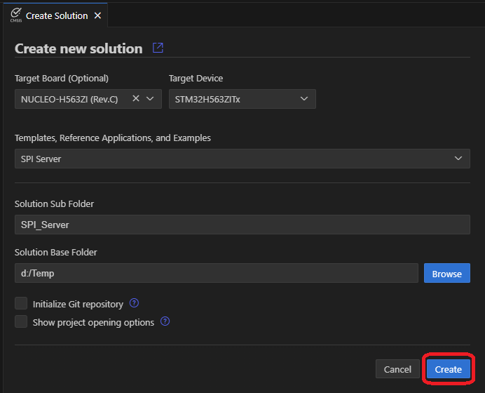
- Choose Solution Base Folder and click Create.
- Build and run the SPI Server application on the STM32F429I-DISC1 board.
SPI1 pinout (STM32F429I-DISC1):
| SPI function | Pin |
| SPI Clock | PA5 |
| Master Output Slave Input (MOSI) | PA7 |
| Master Input Slave Output (MISO) | PB4 |
| Slave Select | PA15 |
- Note
- IMPORTANT: Connect ground between the SPI Server and the Device (Driver) Under Test to ensure a common reference potential.
-
The STM32F429I-DISC1 SPI Server does not support National Semiconductor Microwire frame format.
-
The STM32F429I-DISC1 SPI Server for build-type: Debug displays command execution on an on-board LCD.
Running on specific hardware
Using the Arm CMSIS Solution VS Code extension, create a new solution from template:
- In the CMSIS extension, click Create a New Solution.
- Select the Target Board.
- Under Templates, Reference Applications, and Examples, select SPI Server (CMSIS-Driver Validation SPI Server application).
- Choose Solution Base Folder, click Create.
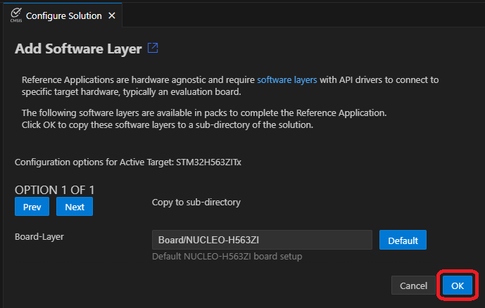
- Select the board layer that provides an SPI Driver, click OK.
- If SPI is not routed to ARDUINO (or a different SPI peripheral is required), open SPI_Server_Config.h, Open Preview and edit Driver_SPI# to the required instance.
- Build and run the SPI Server application on your hardware.
- Note
- IMPORTANT: The target board's SPI CMSIS-Driver must be fully CMSIS compliant!
-
The SPI Server for build-type: Debug displays command execution on an STDOUT channel (typically Virtual COM Port via Debug adapter).
Troubleshooting
- Server not responding
- Reset the Server.
- Verify the correct driver instance in
SPI_Server_Config.h.
- Reduce bus speed used for communication with the Server (in
DV_SPI_Config.h).
- Debug message "Server Start failed!" (build-type: Debug)
- Check heap (must be >
2 * SPI_SERVER_BUF_SIZE).
- Verify RTOS allows >= 512 bytes allocation for the Server main thread (e.g., Global Dynamic Memory size in
RTX_Config.h if RTX5).
- Ensure the Server's SPI driver supports all fixed settings (Slave with hardware-monitored Slave Select, CPOL=0/CPHA=0, 8 bits, MSB to LSB).
- Tests report data mismatch
- Ensure Slave Select line has a pull-up to Vcc (3.3 V).
- Keep wires short and separate; pair SCK and GND if possible.
- Ensure the SPI driver does not drive Slave Select line while inactive.