 |
CMSIS-Zone
Version 1.2.0-alpha
System Resource Management
|
 |
CMSIS-Zone
Version 1.2.0-alpha
System Resource Management
|
This single processor demo application shows how to do the MPU Protection. Using CMSIS-Zone, it generates:
The application itself shows how to isolate network stack threads from the user application.
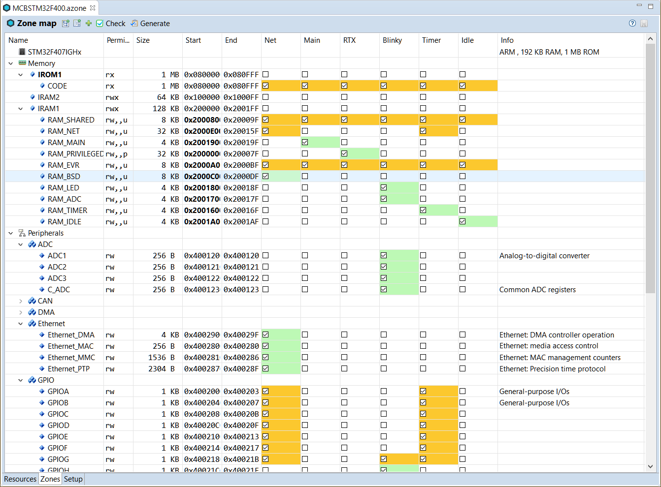
The MCBSTM32F400.azone file of that project has the following configuration settings:
Execution.Net, Main, RTX, Blinky, Timer, Idle CODE, RAM_SHARED, RAM_NET, RAM_MAIN, RAM_PRIVILEGED, RAM_EVR, RAM_BSD, RAM_LED, RAM_ADC, RAM_TIMER, and RAM_IDLE 
The zones use common Flash region for all the application code but different SRAM regions to segregate thread data. To generate the output, click on the Generate button in the Zone Editor tool bar. This creates the following files in the ftl_gen directory:
| Template File | Generated File | Description |
|---|---|---|
| dump_fzone.txt.ftl | dump_fzone.txt | Contains the complete model |
| helper.ftlinc | N/A | Helper template file with FTL functions. |
| mem_layout.h.ftl | mem_layout.h | Header file that contains the memory region definitions, for example for the linker scatter file. |
| mputable.c.ftl | mputable.c | MPU Table data definition. |
| mputable.h.ftl | mputable.h | MPU Table data declaration. |
| scatter.sct.ftl | scatter.sct | Example scatter file for MPU protection. |
These files can be used in any IDE to create the final application. In the following, the usage in Arm Keil MDK is described.
The example project can be loaded, built and debugged in µVision by performing the following steps:
The projects Blinky_Net use the files generated in CMSIS-Zone as follows:
| File | Description |
|---|---|
| mem_layout.h | Input for the linker scatter files. |
| mputable.c | MPU Table data definition. |
| mputable.h | MPU Table data declaration. |
| scatter.sct | Initial template for scatter file. |
As explained previously, the #defines in mem_layout.h can be used to create generic scatter files that are easy to update once changes in the CMSIS-Zone project happen. Using the mem_layout.h file from CMSIS-Zone, the following scatter file is used in the Blinky_Net project, which is based on the generated scatter file template (scatter.sct):
The data segments of segregated software components have been allocated to distinct memory regions.