 |
USB Component
MDK Middleware for USB Device and Host Communication
|

|
|
USB Component
MDK Middleware for USB Device and Host Communication
|
|
The Universal Serial Bus (USB) is a serial interface designed to be plug-and-play making it easy to connect peripherals to a host. The following pages are intended to help the designer to get a better understanding about the USB protocol in general. They are divided into different pages as follows:
USB uses two wires to supply power and two wires to transfer signals. The following data transfer rates are supported:
| Performance | Attributes | Applications |
|---|---|---|
| Low-Speed: 1.5 Mbits/s | Lower cost Hot-pluggable Multiple peripherals | interactive devices: mouse, keyboards, game peripherals |
| Full-Speed: 12 Mbits/s | Low cost Hot-pluggable Multiple peripherals Guaranteed latency Guaranteed bandwidth | phone, audio, compressed video, printers, scanners |
| High-Speed: 480 Mbits/s | Guaranteed latency High bandwidth | video, mass storage |
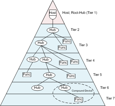
The physical USB network is implemented as a tiered star network with one host (master) and several devices (slaves).
The USB Host provides one attachment port. If more peripherals are required, connect a hub to the root port to provide additional connection ports. The USB network can support up to 127 external nodes. Due to timing constraints for signal propagation, the maximum number of tiers allowed is seven:
USB devices are divided into device classes:
Examples of functions:
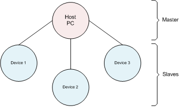
The logical USB network appears as a star network to the developer with the host at the center. Hubs do not introduce any programming complexity and are transparent as far as the programmer is concerned. An USB device will work the same way whether connected directly to a root-hub or whether connected via intermediate hubs. All USB devices are available as addressable nodes in this master/slave network. Only the host can initiate a data transfer in the network.
USB is a polled bus, where the USB Host initiates all data exchanges. The data travels to or from Endpoints in an USB Device. The client in the USB Host stores data in buffers, but does not have endpoints. The USB Host and the peripheral USB Device have distinct layers, as shown in the picture below. The connections between the layers are logical Host-Device interfaces between each horizontal layer. Between the logical connections data is transferred using Pipes.
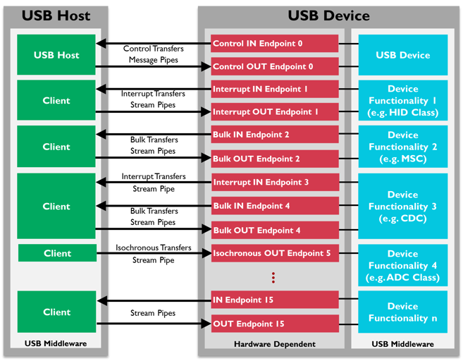
Basically, two types of pipes exist:
Most pipes come into existence when an USB Device has been connected to the USB Bus and configured by the USB Host. A pipe originates from a data buffer within the host client and terminates inside the USB Device at an Endpoint.
Transfers (data flow types) can consist of one or more transactions. A pipe supports only one of the following transfer types:
Control Transfers are bi-directional transfers reserved for the host to send and request configuration information to and from the device using the IN and OUT Endpoint 0.
Each Control Transfer consists of 2 to several transactions. The maximum packet size for the control endpoint data is:
In general, the application software does not use this type of transfer.
Control Transfers have three stages:
Interrupt Transfers have a limited latency to or from a device. In USB, an Interrupt Transfer, or Interrupt Pipe, has a defined polling rate between:
The maximum packet size for the interrupt endpoint data is:
The developer can define how often the host can request a data transfer from the device.
For example, for a mouse, a data transfer rate at every 10 ms can be guaranteed. However, defining the polling rate does not guarantee that data will be transferred every 10 ms, but rather that the transaction will occur somewhere within the tenth frame. For this reason, a certain amount of timing jitter is inherent in an USB transaction.
Typically, Interrupt Transfer data consists of event notifications, characters, or coordinates from a pointing device.
Isochronous Transfers are used for transmitting real-time information such as audio and video data, and must be sent at a constant rate. USB isochronous data streams are allocated a dedicated portion of USB bandwidth to ensure that data can be delivered at the desired rate. An Isochronous pipe sends a new data packet in every frame, regardless of the success or failure of the last packet.
The maximum packet size for the isochronous endpoint data is:
Isochronous Transfers have no error detection. Any error in electrical transmission is not corrected.
Isochronous Transfers are also subject to timing jitters as described for Interrupt Transfers.
Bulk Transfers are used for data which are not of the type Control, Interrupt, or Isochronous. Reliable exchange of data is ensured at the hardware level using error detection.
Data are transferred in the same manner as in Interrupt Transfers, but have no defined polling rate. Bulk Transfers take up all the bandwidth that is available after the other transfers have finished. If the bus is very busy, then a Bulk Transfer may be delayed.
The maximum packet size for the bulk endpoint data is:
For low-speed and full-speed endpoints the following is valid: If the bus is idle, multiple Bulk Transfers can take place in a single 1ms frame (Interrupt and Isochronous Transfers are limited to a maximum of one packet per frame).
For example, Bulk Transfers send data to a printer. As long as the data is printed in a reasonable time frame, the exact transfer rate is not important.
Endpoints can be described as data sources or sinks and exists in USB Devices only. The data stored at an endpoint may either be received from or waiting for being sent to the USB Host. An endpoint can be configured to support four transfer types defined in the USB specification (Control Transfers, Interrupt Transfers, Isochronous Transfers, and Bulk Transfers). Within the limits of the hardware, endpoints can be configured using the USB Middleware (e.g. limit an endpoint to a certain transfer type).
An endpoint acts as a kind of buffer. A USB Host's client may send data to Endpoint 1 for example. Coming from the USB Host, the data will be sent to the OUT Endpoint 1. The program on the microcontroller will then read the data as soon as it is ready to do so. Returning data has to be written to the IN Endpoint 1, as the program cannot access the USB bus freely (the USB bus being controlled by the USB Host). The data in IN Endpoint 1 stays there until the host sends an IN packet to Endpoint 1 requesting the data.
These rules apply to all microcontroller devices:
USB is a polled bus, where the host initiates all data exchanges.
Data is transferred in so called transactions. Normally, they consist of three packets:

In a transaction, data is transferred either from the USB Host to an USB Device or vice-versa. The transfer direction is specified in the token packet that is sent from the USB Host. Then, the source sends a data packet or indicates it has no data to transfer. In general, the destination responds with a handshake packet indicating whether the transfer was successful.

Packets could be thought of as the smallest element of data transmission. Each packet transmits an integral number of bytes at the current transmission rate. Packets start with a synchronization pattern, followed by the data bytes of the packet, and concluded with an End-of-Packet (EOP) signal. All USB packet patterns are transmitted least significant bit first. Before and after the packet, the bus is in idle state.
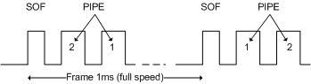
A special packet is the Start-of-Frame packet (SOF) that splits the USB bus into time segments. Each pipe is allocated a slot in each frame. The Start-of-Frame packet is sent every 1ms on full speed links. At high speed, the 1ms frame is divided into 8 microframes of 125μs each. A Start-of-Frame packet is sent at the beginning of each microframe using the same frame number. The frame number increments every 1ms.
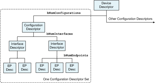
USB devices report their attributes using descriptors, which are data structures with a defined format. Each descriptor begins with a byte-wide field containing the total number of bytes in the descriptor followed by a byte-wide field identifying the descriptor type.
When an USB device is attached to the USB bus, the host uses a process known as bus enumeration to identify and configure the device. The USB Host sends setup requests as soon as the device has joined the USB network. The device will be instructed to select a configuration and an interface to match the needs of the application running on the USB Host. Once a configuration and an interface have been selected, the device must service the active endpoints to exchange data with the USB Host.
This is not a complete list of all the possible descriptors an USB host can request. The usual number of descriptors are:
String Descriptors describe the above mentioned descriptors in human readable format.
Alternative information that is needed when the device can operate in different speed modes can be defined in a Device Qualifier Descriptor.
Complex devices have multiple interfaces. Each interface can have a number of endpoints representing a functional unit. For example, a voice-over-IP phone might have:
Provisions have been made in the USB component to give the user the option to override the USB descriptors if necessary. This can be the case when the device class needs to be changed at run-time or other reports need to be created.
The Device Descriptor (USB_DEVICE_DESCRIPTOR) is the root of the descriptor tree and contains basic device information. The unique numbers, idVendor and idProduct, identify the connected device. The Windows operating system uses these numbers to determine which device driver must be loaded.
idVendor is the number assigned to each company producing USB-based devices. The USB Implementers Forum is responsible for administering the assignment of Vendor IDs.
The idProduct is another 16-bit field containing a number assigned by the manufacturer to identify a specific product.
| Offset | Field | Type | Size | Value | Description |
|---|---|---|---|---|---|
| 0 | bLength | uint8_t | 1 | Number | Size of this descriptor in bytes. |
| 1 | bDescriptorType | uint8_t | 1 | Constant | Device Descriptor Type = 1. |
| 2 | bcdUSB | uint16_t | 2 | BCD | USB Specification Release Number in Binary-Coded Decimal (i.e., 2.10 is 210h). This field identifies the release of the USB Specification with which the device and its descriptors are compliant. |
| 4 | bDeviceClass | uint8_t | 1 | Class | Class code (assigned by the USB-IF). If this field is
|
| 5 | bDeviceSubClass | uint8_t | 1 | SubClass | Subclass code (assigned by the USB-IF). These codes are qualified by the value of the bDeviceClass field. If bDeviceClass is
|
| 6 | bDeviceProtocol | uint8_t | 1 | Protocol | Protocol code (assigned by the USB-IF). These codes are qualified by the value of the bDeviceClass and bDeviceSubClass fields. If a device supports class-specific protocols on a device basis as opposed to an interface basis, this code identifies the protocols that the device uses as defined by the specification of the device class. If this field is
|
| 7 | bMaxPacketSize0 | uint8_t | 1 | Number | Maximum packet size for Endpoint zero (only 8, 16, 32, or 64 are valid). |
| 8 | idVendor | uint16_t | 2 | ID | Vendor ID (assigned by the USB-IF). |
| 10 | idProduct | uint16_t | 2 | ID | Product ID (assigned by the manufacturer). |
| 12 | bcdDevice | uint16_t | 2 | BCD | Device release number in binary-coded decimal. |
| 14 | iManufacturer | uint8_t | 1 | Index | Index of string descriptor describing manufacturer. |
| 15 | iProduct | uint8_t | 1 | Index | Index of string descriptor describing product. |
| 16 | iSerialNumber | uint8_t | 1 | Index | Index of string descriptor describing the device's serial number. |
| 17 | bNumConfigurations | uint8_t | 1 | Number | Number of possible configurations. |
The Configuration Descriptor (USB_CONFIGURATION_DESCRIPTOR) contains information about the device power requirements and the number of interfaces it can support. A device can have multiple configurations. The host can select the configuration that best matches the requirements of the application software.
| Offset | Field | Type | Size | Value | Description |
|---|---|---|---|---|---|
| 0 | bLength | uint8_t | 1 | Number | Size of this descriptor in bytes. |
| 1 | bDescriptorType | uint8_t | 1 | Constant | Configuration Descriptor Type = 2. |
| 2 | wTotalLength | uint16_t | 2 | Number | Total length of data returned for this configuration. Includes the combined length of all descriptors (configuration, interface, endpoint, and class or vendor specific) returned for this configuration. |
| 4 | bNumInterfaces | uint8_t | 1 | Number | Number of interfaces supported by this configuration. |
| 5 | bConfigurationValue | uint8_t | 1 | Number | Value to select this configuration with SetConfiguration(). |
| 6 | iConfiguration | uint8_t | 1 | Index | Index of string descriptor describing this configuration. |
| 7 | bmAttributes | uint8_t | 1 | Bitmap | Configuration characteristics
A device configuration that uses power from the bus and a local source reports a non-zero value in bMaxPower to indicate the amount of bus power required and sets D6. The actual power source at run-time can be determined using the GetStatus(DEVICE) request. If a device configuration supports remote wakeup, D5 is set to 1. |
| 8 | bMaxPower | uint8_t | 1 | mA | Maximum power consumption of the USB device from the bus in this specific configuration when the device is fully operational. Expressed in 2mA units (i.e., 50 = 100mA). |
The Interface Descriptor (USB_INTERFACE_DESCRIPTOR) defines the collection of endpoints. This interface supports a group of pipes that are suitable for a particular task. Each configuration can have multiple interfaces. The interface can be selected dynamically by the USB Host. The Interface Descriptor can associate its collection of pipes with a device class, which in turn has an associated class device driver within the host operating system. Typically, the device class is a functional type such as a printer class or mass storage class.
An interface descriptor never includes Endpoint 0 in the numbering of endpoints. If an interface uses only Endpoint 0, then the field bNumEndpoints must be set to zero.
If no class type has been selected for the device, then none of the standard USB drivers is loaded, and the developer has to provide its own device driver.
| Offset | Field | Type | Size | Value | Description |
|---|---|---|---|---|---|
| 0 | bLength | uint8_t | 1 | Number | Size of this descriptor in bytes. |
| 1 | bDescriptorType | uint8_t | 1 | Constant | Interface Descriptor Type = 4. |
| 2 | bInterfaceNumber | uint8_t | 1 | Number | The number of this interface. Zero-based value identifying the index in the array of concurrent interfaces supported by this configuration. |
| 3 | bAlternateSetting | uint8_t | 1 | Number | Value used to select an alternate setting for the interface identified in the prior field. Allows an interface to change the settings on the fly. |
| 4 | bNumEndpoints | uint8_t | 1 | Number | Number of endpoints used by this interface (excluding endpoint zero).
|
| 5 | bInterfaceClass | uint8_t | 1 | Class | Class code (assigned by the USB-IF).
|
| 6 | bInterfaceSubClass | uint8_t | 1 | SubClass | Subclass code (assigned by the USB-IF). If bInterfaceClass
|
| 7 | bInterfaceProtocol | uint8_t | 1 | Protocol | Protocol code (assigned by the USB). If an interface supports class-specific requests, this code identifies the protocols that the device uses as defined in the device class.
|
| 8 | iInterface | uint8_t | 1 | Index | Index of string descriptor describing this interface. |
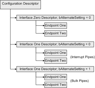
For example, two devices with different interfaces are needed.
The first interface, Interface0, has the field bInterfaceNumber set to 0. The next interface, Interface1, has the field bInterfaceNumber set to 1 and the field bAlternativeSetting also set to 0 (default). It is possible to define an alternative setting for this device, by leaving the field bInterfaceNumber set to 1 and with the field bAlternativeSetting set to 1 instead of 0.
The first two interface descriptors with bAlternativeSettings equal to 0 are used. However, the host can send a SetInterface() request to enable the alternative setting.
The Endpoint Descriptor (USB_ENDPOINT_DESCRIPTOR) specifies the transfer type, direction, polling interval, and maximum packet size for each endpoint. Endpoint 0 (zero), the default endpoint, is always assumed to be a control endpoint and never has a descriptor.
| Offset | Field | Type | Size | Value | Description |
|---|---|---|---|---|---|
| 0 | bLength | uint8_t | 1 | Number | Size of this descriptor in bytes. |
| 1 | bDescriptorType | uint8_t | 1 | Constant | Endpoint Descriptor Type = 5. |
| 2 | bEndpointAddress | uint8_t | 1 | Endpoint | The address of the endpoint on the USB device described by this descriptor. The address is encoded as follows:
|
| 3 | bmAttributes | uint8_t | 1 | Bitmap | The endpoint attribute when configured through bConfigurationValue.
For non-isochronous endpoints, bits 5..2 must be set to zero. For isochronous endpoints, they are defined as:
All other bits are reserved and must be reset to zero. |
| 4 | wMaxPacketSize | uint16_t | 2 | Number | Is the maximum packet size of this endpoint. For isochronous endpoints, this value is used to reserve the time on the bus, required for the per-(micro)frame data payloads.
For high-speed isochronous and interrupt endpoints:
|
| 6 | bInterval | uint8_t | 1 | Number | Interval for polling endpoint for data transfers. Expressed in frames or micro-frames depending on the operating speed (1ms, or 125μs units).
|
A high-speed capable device that has different device information for full-speed and high-speed must have a Device Qualifier Descriptor (USB_DEVICE_QUALIFIER_DESCRIPTOR). For example, if the device is currently operating at full-speed, the Device Qualifier returns information about how it would operate at high-speed and vice-versa.
The fields for the vendor, product, device, manufacturer, and serial number are not included. This information is constant for a device regardless of the supported speeds.
If a full-speed only device receives a GetDescriptor() request for a device_qualifier, it must respond with a request error. Then, the host must not make a request for an other_speed_configuration descriptor.
| Offset | Field | Type | Size | Value | Description |
|---|---|---|---|---|---|
| 0 | bLength | uint8_t | 1 | Number | Size of this descriptor in bytes. |
| 1 | bDescriptorType | uint8_t | 1 | Constant | Device Qualifier Descriptor Type = 6. |
| 2 | bcdUSB | uint16_t | 2 | BCD | USB Specification Release Number in Binary-Coded Decimal (i.e., 2.10 is 210h). This field identifies the release of the USB Specification with which the device and its descriptors are compliant. At least V2.00 is required to use this descriptor. |
| 4 | bDeviceClass | uint8_t | 1 | Class | Class code (assigned by the USB-IF). If this field is
If this field is set to FFh, the device class is vendor specific. |
| 5 | bDeviceSubClass | uint8_t | 1 | SubClass | Subclass code (assigned by the USB-IF). These codes are qualified by the value of the bDeviceClass field. If bDeviceClass is
|
| 6 | bDeviceProtocol | uint8_t | 1 | Protocol | Protocol code (assigned by the USB-IF). These codes are qualified by the values of the bDeviceClass and bDeviceSubClass fields. If a device supports class-specific protocols on a device basis as opposed to an interface basis, this code identifies the protocols that the device uses as defined by the specification of the device class. If this field is
|
| 7 | bMaxPacketSize0 | uint8_t | 1 | Number | Maximum packet size for other speed. |
| 8 | bNumConfigurations | uint8_t | 1 | Number | Number of other-speed configurations. |
| 9 | bReserved | uint8_t | 1 | Zero | Reserved for future use, must be zero. |
String descriptors (USB_STRING_DESCRIPTOR) are optional and add human readable information to the other descriptors. If a device does not support string descriptors, all references to string descriptors within device, configuration, and interface descriptors must be set to zero.
String descriptors are encoded in Unicode so that multiple languages can be supported with a single product. When requesting a string descriptor, the requester specifies the desired language using a 16-bit language ID (LANGID) defined by the USB-IF. String index zero is used for all languages and returns a string descriptor that contains an array of two-byte LANGID codes supported by the device.
The array of LANGID codes is not NULL-terminated. The size of the array (in byte) is computed by subtracting two from the value of the first byte to the descriptor.
| Offset | Field | Type | Size | Value | Description |
|---|---|---|---|---|---|
| 0 | bLength | uint8_t | N + 2 | Number | Size of this descriptor in bytes. |
| 1 | bDescriptorType | uint8_t | 1 | Constant | String Descriptor Type |
| 2 | wLANGID[0] | uint8_t | 2 | Number | LANGID code zero (for example 0x0407 German (Standard)). |
| ... | ... | ... | ... | ... | ... |
| N | wLANGID[x] | uint8_t | 2 | Number | LANGID code zero x (for example 0x0409 English (United States)). |
The UNICODE string descriptor is not NULL-terminated. The string length is computed by subtracting two from the value of the first byte of the descriptor.
| Offset | Field | Type | Size | Value | Description |
|---|---|---|---|---|---|
| 0 | bLength | uint8_t | 1 | Number | Size of this descriptor in bytes. |
| 1 | bDescriptorType | uint8_t | 1 | Constant | String Descriptor Type |
| 2 | bString | uint8_t | N | Number | UNICODE encoded string. |