 |
MDK-Middleware
Software Components for MDK
|

|
|
MDK-Middleware
Software Components for MDK
|
|
The MDK-Middleware examples are implemented as CMSIS-Toolbox Reference Applications that use CMSIS-Driver interfaces. These Reference Applications are hardware agnostic and need to be extended with a compatible board layer to run on a specific hardware target.
Several Board Support Packs (BSP) contain board layers that support the MDK-Middleware components. Refer to the Overview page of the pack to check the Provided connection API Interface of the layers. When such a board layer is not available, it is possible to create a compatible board layer.
The examples are provided as part of the MDK-Middleware pack and maintained as part of its GitHub repository, see Access to MDK-Middleware.
For a detailed list of available examples and their detailed description, see the Examples section in the component documentation.
This chapter gives a generic overview on how to access, configure and build an MDK-Middleware example project for your target hardware.
This section explains how to use MDK-Middleware with the Arm CMSIS Solution for VS Code. This extension is for example part of Keil Studio.
An MDK-Middleware reference example can be selected in the Create a new solution dialog for boards with layers in the BSP.
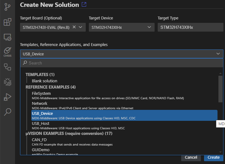
Once the csolution project is loaded the VS Code IDE presents you with a dialog that lets you select a compatible software layer and a compiler toolchain that is available on your computer.
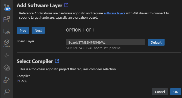
Notes:
- The Add Software Layer dialog only appears when the BSP contains a board layer with compatible API Interfaces (see next section).
- ST board layers are configured for the Arm Compiler (AC6) using STM32CubeMX. However, it is easy to reconfigure for different compilers. The steps are provided in the BSP overview.
The MDK-Middleware Reference Applications are hardware agnostic but require API Interfaces that are expressed using the csolution project connections: node. The various reference applications consume the following API Interfaces. These interfaces should be provided by the board layer that is part of the Board Support Pack (BSP).
| Consumed API Interface | Description |
|---|---|
| File System | . |
| CMSIS_MCI | CMSIS-Driver MCI Interface to memory. |
| STDIN, STDOUT | Standard I/O for user input/output via UART. |
| Network | . |
| CMSIS_ETH | CMSIS-Driver Ethernet MAC/PHY Interface. |
| CMSIS_VIO | CMSIS-Driver VIO connected to LEDs and button |
| STDOUT | Standard I/O connected for printf messages. |
| USB Device | . |
| CMSIS_USB_Device | CMSIS-Driver USB Device Interface. |
| CMSIS_VIO | CMSIS-Driver VIO connected to LEDs and button |
| CMSIS_USART | CMSIS-Driver USART for VirtualCOM project. |
| USB Host | . |
| CMSIS_USB_Host | CMSIS-Driver USB Host Interface. |
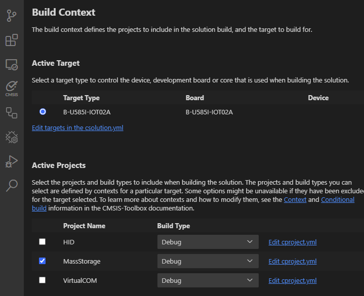
The MDK-Middleware Reference Applications are typically bundles of several similar projects. Use the command CMSIS:Manage Solution Settings to choose a one project that you want to explore.
The steps to add a custom hardware configuration are:
Open the *.csolution.yml file and add a new target-type.
Note:
- You may copy an existing board layer as starting point. But typically these board layers support a range of reference applications and contain driver API interfaces that may be removed.
The uVision Debugger offers advanced debug features such as Event Recorder and Component Viewer to analyze the MDK-Middleware.
To call uVision with the csolution project that you are using in VS Code, create a file .vscode/tasks.json with the content as in the code snippet below. The command: is the path to the uVision executable on your computer.
Note: If the file
.vscode/tasks.jsonalready exists then just add the part between{and}from the code snippet above.
Use the VS Code menu command Terminal - Run Task... to Start uVision. uVision can directly load csolution projects. After you have configured the debugger for your target system you may use the Debug Windows and Dialogs to validate your application.
Refer to Application Note 320: Using Event Recorder for debugging a network performance issue for an tutorial on how to analyze MDK-Middleware issues.
The MDK-Middleware components have extensive debug capabilities. For example, the Network component offers debug output via STDOUT (printf) and/or annotations for the Event Recorder. Each component has therefore a section Create Applications » Debugging. These debug features are today fully supported by the uVision Debugger.
By default, the MDK-Middleware examples are not configured for debugging. The steps below explain how to add these debug capablities.
Enable Event Recorder:
The Event Recorder functionality is provided by the pack ARM::CMSIS-View. Add this pack and the related software component to the cproject.yml file:
<component>_Debug.h (for example Network_Debug.h) configuration file.RTX_Config.h.The board layers may configure STDOUT to a UART port. In some cases, it might be desired to redirect printf output to the Event Recorder.
Disable "Custom" Output:
Remove the following components and the related file retarget_stdio.c in the *.clayer.yml or *.cproject.yml file.
In the source code of the application (usually in the file main.c) remove the call to stdio_init().
Add the pack ARM::CMSIS-Compiler and the related components to the file *.clayer.yml or *.cproject.yml as shown below.
Refer to CMSIS-Compiler for more information about I/O retargeting.
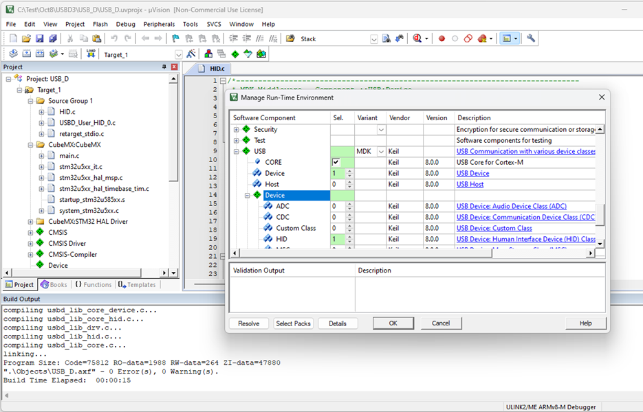
The uVision v5.41 IDE or higher allows to directly work with csolution projects. Source code can be modified, build commands can be executed, and after configuration the uVision Debugger can be used. Adding files or software components is possible by modifying the csolution project yml files. It is not directly supported with a user interface.
As uVision IDE is easy-to-use and powerful many developers want to use this IDE for productive software development. The MDK-Middleware Reference Applications can be recreated as clean, native uVision project by following the steps listed below, once configured with a compatible board layer. Such a board layer can be copied from an existing working csolution project in VS Code by following the section Using VS Code above, or from an existing BSP pack that contains a board layer.
*.cproject.yml of the MDK-Middleware Reference Application and *.clayer.yml of the software layer e.g. the board layer into the new µVision project using the uVision dialogs.These steps are described in more detail below.
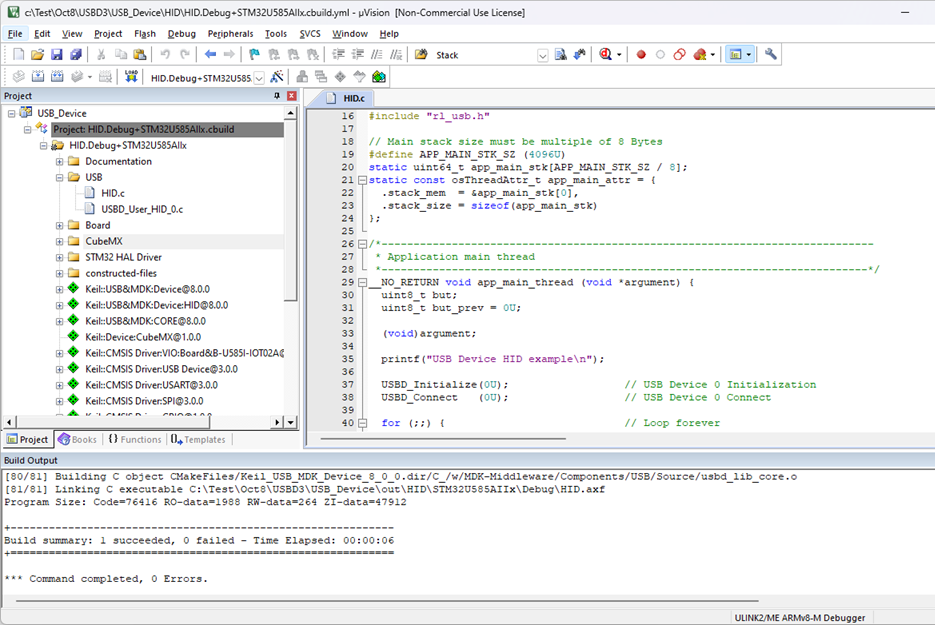
MDK-Middleware Reference Applications contain a collection of projects. The steps below are exemplified on the USB Device HID project.
The tables contain two different use cases:
./Layers/Default/ contains board layer files.Create a new folder for the µVision project and copy the source files from the MDK-Middleware Reference Application.
| From csolution project | Copy to new uVision project folder | Notes |
|---|---|---|
./HID | <MyFolder>/HID | Only copy content from the root directory without subfolders |
./Board/<board_name> | <MyFolder>/Board/<board_name> | Only copy source files (*.c and *.h) from the root directory without subfolders |
| . | . | . |
| From packs | copy to new uVision project folder | Notes |
./Examples/USB/Device/HID from MDK-Middleware pack | <MyFolder>/HID | Only copy content from the root directory without subfolders |
./Layers/.../ from BSP pack | <MyFolder>/Board/<board_name> | Only copy source files (*.c and *.h) from the root directory without subfolders |
From the uVision menu use Project - New uVision Project... dialog to select the device that you are using and create a new µVision project.
The *.cproject.yml of the reference application and *.clayer.yml of the software layer, e.g. board layer contain a list of source files and components that should be added to the new uVision project.
Note:
- Do not start a generator such as STM32CubeMX at this step as the configuration files are copied in the next step.
The RTE configuration files and generator files (for STM32CubeMX or MCUXpresso Config) are fully compatible with uVision. Follow the table below to copy these configuration files to the µVision project folder
| From csolution project | copy to new uVision project folder | Notes |
|---|---|---|
./HID/RTE | <MyFolder>/RTE | Only copy component folders excluding folders that start with _ |
./Board/<board_name>/RTE | <MyFolder>/RTE | Only copy component folders excluding folders that start with _ |
./Board/<board_name/CubeMX> | <MyFolder>/STM32CubeMX/<uVision_target_name> | Rename the *.cgen.yml file |
| . | . | . |
| From packs | copy to new uVision project folder | Notes |
./Examples/USB/Device/HID/RTE from MDK-Middleware pack | <MyFolder>/RTE | Only copy component folders excluding folders that start with _ |
./Layers/Default/RTE from BSP pack | <MyFolder>/RTE | Only copy component folders excluding folders that start with _ |
./Layers/Default/CubeMX from BSP pack | <MyFolder>/STM32CubeMX/<uVision_target_name> | Rename the *.cgen.yml file (see note below) |
Note:
- The
*.cgen.ymlfile copied from the existing csoution project or from the BSP pack must be renamed to match your µVision project name, i.e.<MyProject>.cgen.yml.
The compiler toolchain relevant settings of the csolution project are in the *.csolution.yml and *.cproject.yml files. Based on these settings configure compiler toolchain in uVision using the tabs of the Options dialog:
Software Model: TrustZone Off.-O1 (for Debug), -O3 (for Release), Warnings: AC5-like, Language C: C11.board_name.h, which can be found in ./Board/<board_name>. This board_name.h should be set as the value of a preprocessor symbol CMSIS_target_header in Options for Target - C/C++(AC6) - Preprocessor Symbols 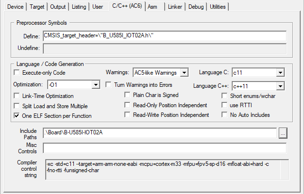
.\tmp\1\ac6_linker_script.sct. Copy this file to <MyFolder>/Board/<board_name> and add it as Scatter File.ac6_linker_script.sct.src from the directory <cmsis-toolbox-installation-dir>/etc of the CMSIS-Toolbox.<MyFolder>/Board/<board_name>.ac6_linker_script.sct.src the following statements to enable the linker integrated C preprocessor:cdefault.yml included in some MDK-Middleware Reference Applications there may be some linker controls that should be reflected in this dialog, for example --diag_suppress=L6314W.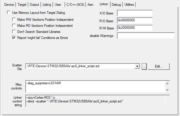
Once the new project is created, it may be expanded with additional software components or modified to custom hardware as shown in the picture below. Note that uVision projects have no dependency on specify hardware boards.