 |
OpenGL ES SDK for Android
ARM Developer Center
|
|
OpenGL ES SDK for Android
ARM Developer Center
|
Basic lighting using OpenGL ES 2.0.
The source for this sample can be found in the folder of the SDK.
This tutorial will take the application we created in Simple Cube and teach you how to add lighting to it. No changes are needed to the Java side of the application, all the changes that happen are on the native side.
For the tutorial, the Simple Cube project will be used as a starting point. So either copy the project or create a completely new project and include the source files from the previous project. The project should be called Lighting and the package name should be called com.arm.malideveloper.openglessdk.lighting. Finally, the activity class (previously SimpleCube.java) should be renamed Lighting.java using Eclipse (this ensures references to the activity get updated elsewhere in the project).
So far we have just rendered our objects with simple colours. From a lighting point of view, everything in the scene is fully lit, it has exactly the colour we specified. To make the scene more realistic we have to introduce the concept of lights to the scene. In this tutorial we will introduce the concepts of vertex normals and diffuse, specular, and ambient light.
OpenGL ES 2.0 onwards does not have a concept of lights. It is up to the developer to devise and implement a method for simulating light within a scene. Like everything in computer graphics, lighting is faked. This means that instead of attempting to accurately model the flow of photons throughout the scene (see: ray-tracing), we are instead going to use an approximation which gives "good-enough" results.
What we are going to implement here is a directional light and we're going to do the calculations per vertex. There are certain limitations to this approach that we take a look at along the way. We will be making certain assumptions about the scene, the lights, and the materials being used to make this tutorial as simple as possible. These will be pointed out as we go.
We are going to using the Phong reflection model as the basis for this tutorial, see Wikipedia for more information.
Before we get stuck into the interesting parts of this tutorial we must first add a few bits to make it easier later on. Because, traditionally, lighting a cube correctly is quite tricky (it doesn't necessarily show off the effects very nicely), we're going to turn the cube into a very simple approximation of a sphere.
All the changes we're going to make in this tutorial are inside Native.cpp.
To this end, we are going to add some extra geometry. We're going to add an extra vertex per face, right in the middle of each face but sticking out a bit more. The vertices array should now look like this:
To make sure the vertices are coloured correctly we need to add an extra colour per face in our colour array:
To make use of these new vertices, we need to adjust the indices into our vertex array to draw the correct triangles. We are now going to draw four triangles per face, all of which will use the vertex we added in the middle of the face. Take care to remember that the winding of the vertices is important (front facing polygons must have anti-clockwise winding).
The indicies array should now look like this:
Lastly in renderFrame, we need to increase the number of vertices drawn in our draw call (from 36 to 72) because we are drawing twice as many triangles. So it looks like this:
For most lighting models, it's important to know which way all of the polygons in your scene are facing. For example, if we know a light is pointing from a certain direction, in order to know whether a polygon should be lit by that light we must know if it's facing towards the light or not. So, you may be thinking, the system should know which way the polygon is facing because we specified it. We specified the vertices with the correct winding to show which way we wanted them to face and we provide a transformation to move the polygons to the correct place.
There are two reasons we don't use this information:
We use what are known as "surface normals" or just "normals" to encode the required information. For every vertex in the scene we provide a vector which points perpendicularly from the surface it represents.
To send this data to the GPU we use the exact same mechanism as for sending colour data and position data to the GPU. We define an array with per vertex normals in it, we get the location of the normals variable in the vertex shader and then upload the data to the GPU using glVertexAttribPointer and glEnableVertexAttribArray.
We add an attribute in the vertex shader for the vertex normals:
Create a global variable to hold vertex normal attribute location:
Get the location of this attribute from the host side in setupGraphics:
Create an array with all the vertex normals in it (like for vertex positions and colours):
Upload the data to the GPU every frame in renderFrame:
The vertex normal array would usually be generated by a modelling tool alongside your vertex positions. We've created them by hand here to match the vertex positions we've specified. You may notice that in our normals array the normals are not strictly perpendicular to the polygons they are connected to. This is so we can show off all of the light techniques we present here, in particular Specular Light. For more information, see Messing with Normals.
If we think about a directional light at its most simple, we want to work out whether the light would touch the face of our polygon. If we store the direction of the light as a vector there is a simple calculation which will give us that data. The dot product of two normalised vectors will give you the cosine of the angle between those vectors (see http://en.wikipedia.org/wiki/Dot_product).
Therefore, the dot product of the light direction and the surface normal will give us the cosine of the angle between those vectors. If this angle is between -90° (270°) and 90° the light is on the correct side of the polygon. Since the return value of dot is actually the cosine of the angle we actually want to check to see if it's between cos(90°) and cos(-90°) or in fact just greater than zero (cos(90°) = cos(-90°) = 0).
Figure 2 shows that the dot product of any vector on the front face of the surface will be positive. N** is the normal to the surface, and the other three vectors represent lights (with their directions reversed so that the dot product gives the correct angle). For the red and orange lights, the dot product returns cos(45°) and cos(295°) respectively, which are both positive values. The dot product of the normal and the green light vector is cos(155°); a negative number.
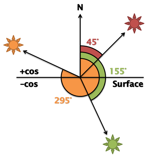
This would give us a binary on or off for our light, but we can to better than that. If we use the angle to directly control the intensity of the light, the surface will be brighter when the surface is more directly facing the light (e.g. cos(0°) = 1) reducing as the angle increases (e.g. cos(80°) = 0.17).
Again, looking at figure 2, the dot product of the red light and the normal (cos(45°) = 0.71) is greater than the dot product of the orange sun and the normal (cos(295°) = 0.42).
To do this in our shaders we need to make the following changes to the vertex shader, add these lines at the top of the main function:
In the same way that we transform the vertex positions by the modelViewMatrix we must also transform the normals so that they match up. Because normals are vectors (rather than positions) we set the w component of the normals to 0. This means that any translations in the model view matrix are ignored.
We then set up the light direction. As mentioned, the maths requires that the light direction is reversed so this is actually the direction opposite where we want the light to point. In a real world application you might pass the light direction in as a attribute and transform it by a matrix, but here we are keeping things simple.
Lastly, we set the fragment colour to zero, we will be incrementing this with different types of lighting as we go.
To actually do the diffuse calculation we need the following code:
First we have the RGB intensity of the diffuse component of the light (we will see there are more components later). This lets you set the colour of the light (in our case it's a white light).
Then we set an RGB constant to describe what ratio of the diffuse light this surface should reflect. (between 0 and 1) This allows us to set the colour of the surface. For example, setting the ratio to (1.0, 0.0, 0.0) means that 100% of the red light will be reflected with 0% of the green and blue light, setting the colour of the objects to red. In this example, we can just use the vertex colours we already have for the ratio, as it will give us the desired result. In a real application however, each material type in a scene would usually define separate ratios for each of the different light components.
Next we do the dot product of the normal and light direction to get the cosine of the angle between the two. The call to max ensures that negative values (when the light is behind the surface) are ignored.
And lastly, we combine them all to together and add the result to the fragment colour.
One assumption we are making here is that the light is "parallel". For a normal spotlight, the light points at a particular spot and the further away from that spot you go the less light there is; the light is spread out like a cone. In our model, that's not the case, the light simply has a direction. This turns out to be surprisingly useful approximation though, since if a light source is sufficiently far away (e.g. the sun) then the light rays can be treated as if they are parallel rather than in a cone.
So that's great for light falling on the object directly from our light source, but what about light that's reflected from our objects in the scene? In the real world, even when things are in shadow, they are very rarely ever completely black, light reflects off almost all objects so that areas not in direct view of a light source still get touched by reflections. Modelling these interactions is what's known as "global illumination". To do this in a physics-correct way would be very complex and computationally expensive. One very easy and cheap way to simulate this is to use Ambient Light. Basically, we define that everything in the scene is hit by a very small uniform amount of light.
To do this, we add this to the vertex shader:
This sets the RGB ambient light intensity (how much reflected light there is in the scene in our simple global illumination approximation).
It then sets an RGB constant to describe what ratio of the ambient light this surface should reflect (like the diffuse constant above). Again we are using the vertex colour for simplicity, but this would normal be specified separately.
Lastly it simply multiples the two and adds it to the accumulating fragment colour. This means that regardless of the surface normal, light direction, and eye direction, every polygon rendered will have some light on it.
Finally, we want to to deal with the reflective or shiny nature of surfaces. For example, a shiny metallic surface and a matte wooden surface of the same colour will look different even if the light direction, light intensity, eye position and surface orientation are the same. Just using diffuse and ambient light as we have so far would mean that the surfaces look the same. What we have to take into account is the amount of light reflected from the surface directly towards the eye.
We can do this by first finding out which way the light is reflecting off the surface and then doing the dot product of that vector and the inverse eye direction.
Figure 3 shows that if we find a reflection vector R where Ω = Θ, we can use this with the inverse eye direction to find find Φ. We can use Φ to control the intensity of specular light reflecting from the surface to simulate how much light is being reflected directly towards the eye.
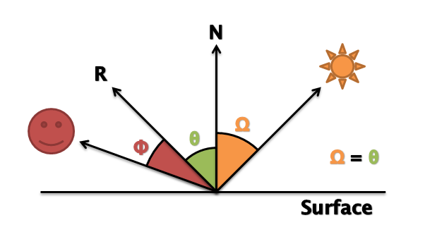
Helpfully, OpenGL ES SL includes a reflect function which takes an incident vector (we will use the light direction), and a surface normal (N) and gives you the reflected direction (R).
In the vertex shader, we add:
As we have said, the eye direction is crucial to calculating specular lighting. Like with the light direction the maths requires the eye direction to be reversed so we specific the inverse eye direction instead. Also like the light direction, you would probably want to pass the eye direction in as a attribute and transform it by a camera matrix, but again, here we are keeping things simple.
Like for ambient and diffuse light we have an RGB light intensity and an RGB specular reflection constant. Unlike ambient and diffuse (where we used the vertex colour as the constant) here we set the value to (1.0, 1.0, 1.0) this means that when R is equal to the eye vector, the specular colour will be exactly (1.0, 1.0, 1.0). This gives us a nice white highlight at this point.
The shininess parameter controls how "tight" the highlight is. We use this as the exponent for the dot product of the two vectors later. Since the dot product is always between 0 and 1 (thanks to the max function), the higher the exponent, the small the result of that pow calculation will be. This means that the specular value will decrease more rapidly as R moves away from the eye vector.
We use the reflect function to find the value of R (using vec3(0) - inverseLightDirection as in this case we want the actual light direction).
Then we do the dot product of R and the eye vector and lastly multiply everything together to calulate the specular contribution.
So, to put it all together in the vertex shader looks like this:
Note that at the end we are clamping the fragment colour between 0 and 1 since that is the maximum colour values. We are also calculating the vertex positions as before in Simple Cube.
This is not the most optimal way of doing this, it's a simplified version designed to be easy to understand. If you were to take this forward you would probably want to define the following outside of the shader and pass them in:
For multiple lights you will need multiple light directions and light intensities for each one. To have different types of materials in your scene with different reflective properties, you will need to have the specular, diffuse, and ambient reflection constants for each separate material.
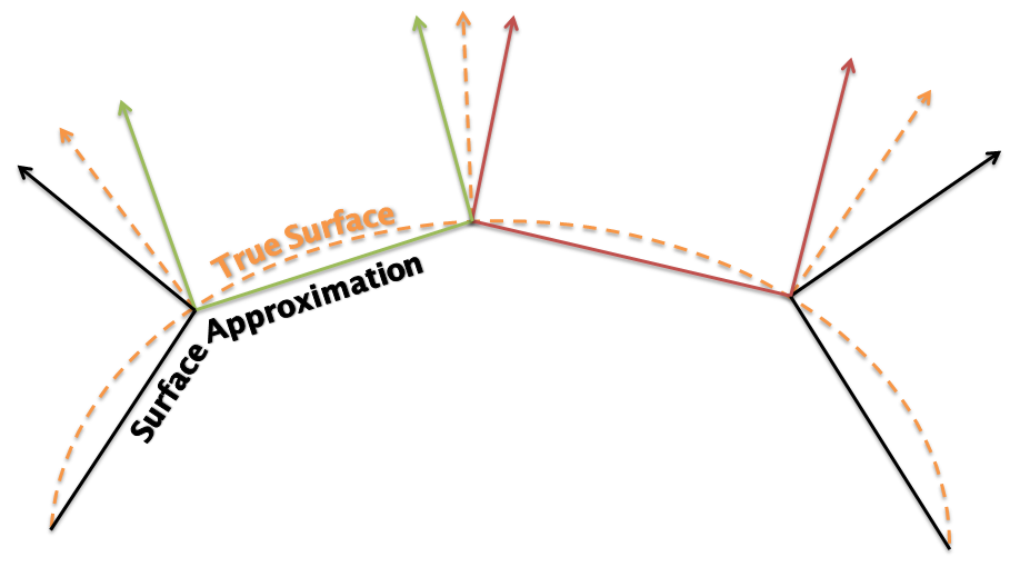
Now that you've seen how normals influence lighting in a scene, you might realise that since we have complete control over the entire system we can achieve more effects using normals. If our normals are strictly perpendicular to the polygon in the scene, the polygons will be lit accordingly, and all the polygons will be individually visible. Maybe this is what we want, but more commonly we are trying to represent a smooth surface and the polygons are just an approximation of that surface. Therefore if we make the normals perpendicular to the original surface rather that our approximation, the lighting will behave as if we had a more complex representation and the surface will look more like what we originally intended.
We can see this in Figure 3, the dashed line is the surface you want to represent, the solid line is how your might approximate it with polygons. The solid vectors are the true normals for the approximated surface, i.e. they are perpendicular to the geometry. The dashed vectors are the normals to the true surface at the same points. So, if we use the approximate surface with the true surface normals. We get a cheaper (to render) geometry with accurate lighting.
That's actually what we have done in this tutorial, because we are approximating a sphere with our shape, we have specified the normals as if it was a curved surface. When the object is spinning, the part in the centre of the screen should be lit as if its a smooth curved surface. What ruins this illusion is of course the flat triangle edges of the object. This can be improved by adding additional geometry.
If we had used accurate normals in this sample, the specular lighting would not have had the same effect. Because each vertex of the polygon would have had the same normal, the specular lighting component would end up being the same for each fragment in the polygon. This would lead to the polygons "flashing" as the eye direction approaches the reflection vector. If you have lots of geometry in the object this would not as noticeable, but on our simple shape it ruins the effect we are trying to achieve.
There are even more things we can do with normals to achieve different effects such as bump mapping, normal mapping and parallax mapping (these effects require moving some of the lighting calculations to the fragment shader).. We'll cover these advanced lighting techniques in future tutorials.
Some points to consider once you have finished this tutorial:
Follow the Getting Started Guide from Building Android samples onwards to build and run the application.

