OpenGL ES SDK for Android ARM Developer Center
 All Classes Namespaces Files Functions Variables Typedefs Enumerations Enumerator Friends Macros Pages
Min Max Blending

The application demonstrates behaviour of blending in GL_MIN and GL_MAX mode in OpenGL ES 3.0.

Introduction

It's assumed that you have read and understood all of the mechanisms described in Asset Loading,Simple Triangle and Texture Cube.

Overview

MinMaxBlending_android.png
The 3D texture presenting a magnetic resonance of a human head

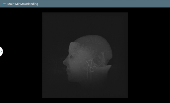
The application demonstrates behaviour of blending in GL_MIN and GL_MAX mode. It renders a 3D texture which consists of a series of greyscaled images obtained from magnetic resonance of a human head. The images are placed one after another in Z axis, so when blending is enabled they imitate a 3D model of the head.

Texture coordinates are then rotated, so viewers can see the model from different perspectives and after each 5 seconds, blending equation is changed. Since U/V/W coordinates are taken from interval <0.0, 1.0> and they are clamped to edge, there might occur some distortions for specific angles of rotation. That is why, the application adds a few blank layers behind and in the front of the original images. Now, if rotated coordinates exceed the interval, only the additional edge layers are repeated creating a noiseless background.

Because images contain a lot of black color, regular min blending would result in having black square on the screen. Hence, there is a threshold applied in fragment shader which prevents rendering fragments that are not bright enough. Additionally, for both types of blending, contrast of output luminance had to be modified to see more details.

To use your own input images, it's check their format and adjust the values of the min blending threshold, luminance of additional edge layers and contrast modifier.

Program Object

In the application there is only one program object used. It's responsible for rendering a 3D texture on screen, rotate it and discard fragments that are not bright enough in case of a min blending option is used. The idea of generating and using program objects, attaching shaders to program object and compiling them should be already well known to the reader. If it isn't, please refer to previous tutorials. Please look into shaders we are using.

Vertex Shader Code

/* Input vertex position. */
in vec4 inputPosition;
/* Input U/V/W texture coordinates. */
in vec3 inputUVWCoordinates;
/* Constant transformation matrices. */
uniform mat4 cameraMatrix;
/* Vector storing rotation coefficients for rotation matrices. */
uniform vec3 rotationVector;
/* Number of instances that are going to be drawn. */
uniform int instancesCount;
/* Output texture coordinates passed to fragment shader. */
void main()
{
/* Matrix rotating texture coordinates around X axis. */
mat3 xRotationMatrix = mat3(1.0, 0.0, 0.0,
0.0, cos(radians(rotationVector.x)), sin(radians(rotationVector.x)),
0.0, -sin(radians(rotationVector.x)), cos(radians(rotationVector.x)));
/* Matrix rotating texture coordinates around Y axis. */
mat3 yRotationMatrix = mat3(cos(radians(rotationVector.y)), 0.0, -sin(radians(rotationVector.y)),
0.0, 1.0, 0.0,
sin(radians(rotationVector.y)), 0.0, cos(radians(rotationVector.y)));
/* Matrix rotating texture coordinates around Z axis. */
mat3 zRotationMatrix = mat3( cos(radians(rotationVector.z)), sin(radians(rotationVector.z)), 0.0,
-sin(radians(rotationVector.z)), cos(radians(rotationVector.z)), 0.0,
0.0, 0.0, 1.0);
/* U/V/W coordinates pointing at appropriate layer depending on gl_InstanceID. */
vec3 translatedUVWCoordinates = inputUVWCoordinates - vec3(0.0, 0.0, float(gl_InstanceID) / float(instancesCount - 1));
/*
* Translate from <0.0, 1.0> interval to <-1.0, 1.0> to rotate texture coordinates around their center.
* Otherwise, the rotation would take place around the XYZ axes which would spoil the effect.
* The translated coordinates should be translated back to <0.0, 1.0> after all rotations are done.
*/
translatedUVWCoordinates = translatedUVWCoordinates * 2.0 - vec3(1.0);
/* Rotate texture coordinates. */
translatedUVWCoordinates = xRotationMatrix * translatedUVWCoordinates;
translatedUVWCoordinates = yRotationMatrix * translatedUVWCoordinates;
translatedUVWCoordinates = zRotationMatrix * translatedUVWCoordinates;
/* Translate back to <0.0, 1.0> interval. */
uvwCoordinates = (translatedUVWCoordinates + vec3(1.0)) / 2.0;
/* Calculate Model-View-Projection matrix. */
modelViewProjectionMatrix = projectionMatrix * cameraMatrix;
/* Calculate position of vertex. With each instance squares are drawn closer to the viewer. */
gl_Position = modelViewProjectionMatrix * (inputPosition + vec4(0.0, 0.0, float(gl_InstanceID) / float(instancesCount - 1), 0.0));
}

The vertex shader is responsible for rotating the texture, which in our case means, updating the UVW coordinates for a specific layer of a 3D texture based on the rotation vector value.

Fragment Shader Code

precision mediump float;
precision mediump int;
precision mediump isampler3D;
/* Value used to normalize colour values. */
const highp int maxShort = 32768;
/* Value used to brighten output colour. */
const float contrastModifier = 3.0;
/* Input taken from vertex shader. */
/* 3D integer texture sampler. */
uniform isampler3D textureSampler;
/* Boolean value indicating current blending equation. */
/* Threshold used for min blending. */
/* Output variable. */
out vec4 fragColor;
void main()
{
/* Loaded texture short integer data are in big endian order. Swap the bytes. */
ivec4 initialTexture = ivec4(texture(textureSampler, uvwCoordinates).rrr, 1.0);
ivec4 swappedBytesTextureTemp = (initialTexture << 8) & ivec4(0xFF00);
ivec4 swappedBytesTexture = ((initialTexture >> 8) & ivec4(0x00FF)) | swappedBytesTextureTemp;
/* Determine output fragment colour. */
fragColor = vec4(swappedBytesTexture) / float(maxShort) * contrastModifier;
/* If min blending is set, discard fragments that are not bright enough. */
if (isMinBlending && length(fragColor) < minBlendingThreshold)
{
discard;
}
}

The fragment shader is responsible for sampling the 3D texture and when the min blending mode is used, discarding fragments that are not bright enough.

3D Textures

A 3 dimensional texture is represented by a bunch of 2D textures. To create a 3D texture in OpenGL ES 3.0, you need to:

  1. Create a texture object ID;
    GL_CHECK(glGenTextures(1, &textureID));
  2. Bind it to the GL_TEXTURE_3D target;
    GL_CHECK(glBindTexture(GL_TEXTURE_3D, textureID));
  3. Initialize texture storage;
    /* Initialize storage space for texture data. */
    GL_CHECK(glTexStorage3D(GL_TEXTURE_3D,
    1,
    GL_R16I,
  4. Set the texture object parameters;
    /* Set texture parameters. */
    GL_CHECK(glTexParameteri(GL_TEXTURE_3D, GL_TEXTURE_WRAP_S, GL_CLAMP_TO_EDGE));
    GL_CHECK(glTexParameteri(GL_TEXTURE_3D, GL_TEXTURE_WRAP_T, GL_CLAMP_TO_EDGE));
    GL_CHECK(glTexParameteri(GL_TEXTURE_3D, GL_TEXTURE_WRAP_R, GL_CLAMP_TO_EDGE));
    GL_CHECK(glTexParameteri(GL_TEXTURE_3D, GL_TEXTURE_MAG_FILTER, GL_NEAREST));
    GL_CHECK(glTexParameteri(GL_TEXTURE_3D, GL_TEXTURE_MIN_FILTER, GL_NEAREST));
  5. Fill each of the texture levels with data (the above function should be called for each texture layer).
    /* Set 2D image at the current textureZOffset. */
    GL_CHECK(glTexSubImage3D(GL_TEXTURE_3D,
    0,
    0,
    0,
    1,
    GL_RED_INTEGER,
    GL_SHORT,
    textureData));

Once all of the steps described above are completed, we can use the texture object as an input for the program object 3D uniform sampler. We are using only one sampler object and a default texture unit, so the steps described below are not necessary, but we will issue them anyway, just to show you the mechanism.

First of all, we are querying for locations of a 3D sampler.

GLint textureSamplerLocation = GL_CHECK(glGetUniformLocation(programID, "textureSampler"));

Please note that the second argument should correspond to the uniform name that is used in the shader.

The next step is to check whether the retrieved location is valid. If the returned value is -1, the uniform is considered inactive and any attempt to set the uniform value will be ignored.

ASSERT(textureSamplerLocation != -1, "Could not find location for uniform: textureSampler");

Once we are sure, the uniform has been found, we can set its value. It's achieved by some basic steps.

Set active texture unit (GL_TEXTURE0 is active by default, but we want to call it anyway to show you the mechanism).

GL_CHECK(glActiveTexture(GL_TEXTURE0));

Then, we need to bind a texture object to GL_TEXTURE_3D target.

GL_CHECK(glBindTexture(GL_TEXTURE_3D, textureID));

And now, by calling the function shown below, the texture object named with textureID will be used as an input for the program object.

GL_CHECK(glUniform1i(textureSamplerLocation, 0));

In the glUniform1i() call the second argument corresponds to the 0 in the GL_TEXTURE0 texture unit. If we would like to use 3D texture object which is bound to GL_TEXTURE_3D target at GL_TEXTURE1 texture unit, then the second argument in the glUniform1i() call should be equal to 1.

To draw a 3D texture on screen, we use instanced drawing technique to render each texture layer separately.

/* Draw a single square layer consisting of 6 vertices for textureDepth times. */
GL_CHECK(glDrawArraysInstanced(GL_TRIANGLES, 0, 6, textureDepth));

Blending

The main idea of the application is to show the difference between GL_MIN and GL_MAX blend equations. Just to clarify: the specific blend equation specifies how a pixel color is determined. To be more precise: if a pixel does already have a color determined (it always has) and we want to apply a new color to it, then we can specify how the two colors will be blend: we can simply add the two colors, subtract them or we can use minimum or maximum values of the two (which is our case).

First of all, we need to enable blending. Without that, the new color will replace the old one and no blending will be issued.

/* Enable blending. */
GL_CHECK(glEnable(GL_BLEND));

Then, we can change the blend equation by calling

/* Set new blend equation. */
GL_CHECK(glBlendEquation(GL_MIN));

or

/* Set new blend equation. */
GL_CHECK(glBlendEquation(GL_MAX));

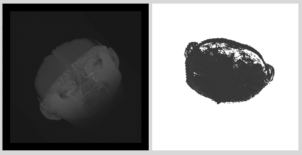
The result of the specific blend equations are shown below.

MinMaxBlending_result.png
The result of different blend equations: GL_MAX (on the left) and GL_MIN (on the right).