OpenGL ES SDK for Android ARM Developer Center
 All Classes Namespaces Files Functions Variables Typedefs Enumerations Enumerator Friends Macros Pages
Terrain Rendering with Geometry Clipmaps

This sample will show you how to efficiently implement geometry clipmaps using OpenGL ES 3.0. The sample makes use of 2D texture arrays as well as instancing to efficiently render an infinitely large terrain. The terrain is asynchronously uploaded to the GPU using pixel buffer objects.

terrain.png

Introduction

Note
This sample uses OpenGL ES 3.0.

The source for this sample can be found in the folder of the SDK.

Note
This sample involves several advanced OpenGL techniques to achieve its goals:
  • Sampling textures in vertex shader
  • Instanced drawing
  • Uniform buffer objects
  • Pixel buffer objects
  • 2D texture arrays
  • A frustum culling technique is applied as well, although that is a purely mathematical technique.

Representing the Terrain

The terrain representation is based on the paper of Losasso and Hoppe [1].

clipmap.png

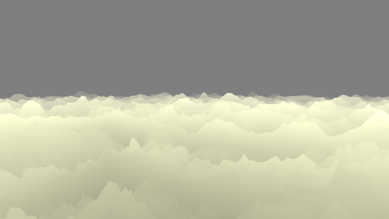
The basic building block of the terrain is a tesselated square with N-by-N (in this implementation, 64-by-64) vertices. A tesselated square can be represented efficiently with a single triangle strip.

Generate vertex data for a block:

GLubyte *pv = vertices;
// Block
for (unsigned int z = 0; z < size; z++)
{
for (unsigned int x = 0; x < size; x++)
{
pv[0] = x;
pv[1] = z;
pv += 2;
}
}

Generate index buffer for a block:

static GLushort *generate_block_indices(GLushort *pi, unsigned int vertex_buffer_offset,
unsigned int width, unsigned int height)
{
// Stamp out triangle strips back and forth.
int pos = vertex_buffer_offset;
unsigned int strips = height - 1;
// After even indices in a strip, always step to next strip.
// After odd indices in a strip, step back again and one to the right or left.
// Which direction we take depends on which strip we're generating.
// This creates a zig-zag pattern.
for (unsigned int z = 0; z < strips; z++)
{
int step_even = width;
int step_odd = ((z & 1) ? -1 : 1) - step_even;
// We don't need the last odd index.
// The first index of the next strip will complete this strip.
for (unsigned int x = 0; x < 2 * width - 1; x++)
{
*pi++ = pos;
pos += (x & 1) ? step_odd : step_even;
}
}
// There is no new strip, so complete the block here.
*pi++ = pos;
// Return updated index buffer pointer.
// More explicit than taking reference to pointer.
return pi;
}

This block lies on the horizontal plane (XZ-plane) and is stitched together in a grid to draw an arbitrarely vast terrain as seen above.

To avoid aliasing and excessive detail in drawing, terrain which is drawn farther away requires lower resolution. This is achieved by scaling up the basic N-by-N block in powers of two.

Note
Like mipmap levels, clipmap level 0 denotes the level with highest detail. In this sample, 10 clipmap levels in total are used.

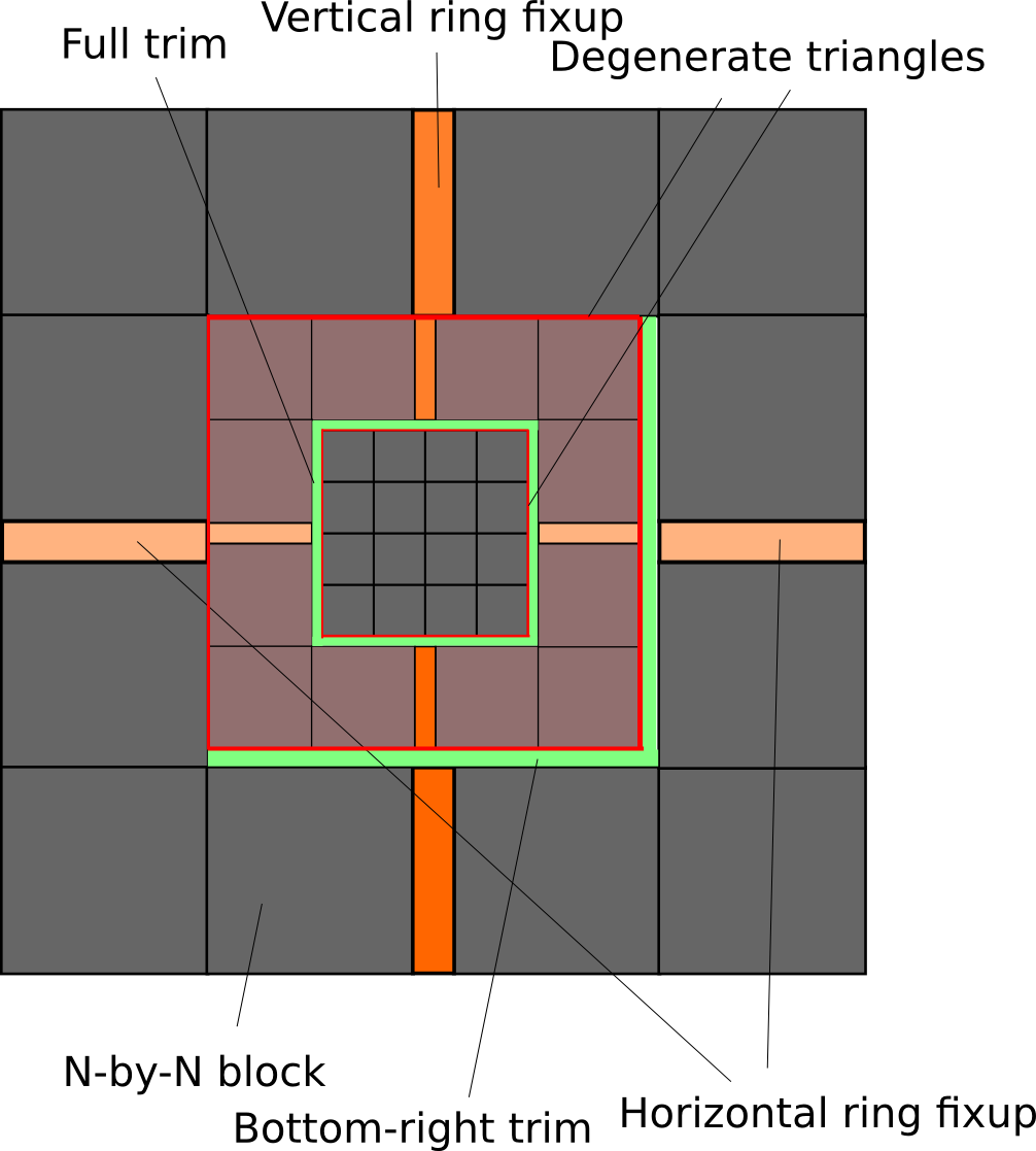
When stitching together the clipmap, there are small holes which must be filled. This is done by drawing smaller "fixup" and/or "trim" regions as seen above. Strips of degenerate triangles must also be drawn on the edges where the clipmap level changes.

The degenerate triangles which connect level N and N + 1 are drawn using vertices from level N. Trim regions which connect level N and N + 1 are drawn using vertices from level N + 1.

The exact layout of blocks must be carefully planned to ensure a seamless terrain. An important thing to note is that the distance between two adjacent N-by-N blocks is N - 1. Most offsets seen in the sample code use this distance with the occasional 2 texel offset to account for the width of the horizontal and vertical fixup regions.

The vertex buffer along with the index buffer is uploaded once to the GPU at startup.

Snapping the Terrain to a Grid

Positions of blocks are moved along with the camera in discrete steps. Moving in discrete steps is important to avoid a vertex "swimming" effect. As the camera moves, lower clipmap levels can change position while higher levels don't and therefore the trim region used to connect two clipmap levels might have to change to be able to fill the entire terrain.

On every frame, clipmap level offsets are computed as such:

// The clipmap levels only move in steps of texture coordinates.
// Computes top-left world position for the levels.
vec2 GroundMesh::get_offset_level(const vec2& camera_pos, unsigned int level)
{
if (level == 0) // Must follow level 1 as trim region is fixed.
return get_offset_level(camera_pos, 1) + vec2(size << 1);
else
{
vec2 scaled_pos = camera_pos / vec2(clipmap_scale); // Snap to grid in the appropriate space.
// Snap to grid of next level. I.e. we move the clipmap level in steps of two.
vec2 snapped_pos = vec_floor(scaled_pos / vec2(1 << (level + 1))) * vec2(1 << (level + 1));
// Apply offset so all levels align up neatly.
// If snapped_pos is equal for all levels,
// this causes top-left vertex of level N to always align up perfectly with top-left interior corner of level N + 1.
// This gives us a bottom-right trim region.
// Due to the flooring, snapped_pos might not always be equal for all levels.
// The flooring has the property that snapped_pos for level N + 1 is less-or-equal snapped_pos for level N.
// If less, the final position of level N + 1 will be offset by -2 ^ N, which can be compensated for with changing trim-region to top-left.
vec2 pos = snapped_pos - vec2((2 * (size - 1)) << level);
return pos;
}
}

Offsets of blocks within a clipmap level are relative to the clipmap level offset.

Sampling Textures in Vertex Shader

OpenGL ES 3.0 added guaranteed support for sampling textures in the vertex shader. This allows the application to dynamically update vertex data in ways which would have been costly with older methods. The vertex buffer is fixed, and never has to be updated. (see advanced_samples/Terrain/jni/shaders.h)

While the vertex buffer represents the fixed grid structure in the horizontal plane, the vertical Y component is dynamic and is sampled from a heightmap texture.

Note
Automatic mip-mapping cannot be used in vertex shaders (no derivatives). If sampling from a mip-mapped texture, an explicit level-of-detail must be provided, by using e.g. textureLod. In this sample however, mipmapped textures are not used, so using texture directly is safe.

Heightmap Representation

Each clipmap level is backed by its own 255x255 texture. As the size for each level is the same, it is convenient and efficient to use a 2D texture array, introduced in OpenGL ES 3.0. Using a texture array avoids having to bind different textures for drawing different clipmap levels which reduces the number of draw calls required.

GL_CHECK(glGenTextures(1, &texture));
GL_CHECK(glBindTexture(GL_TEXTURE_2D_ARRAY, texture));
// Use half-float as we don't need full float precision.
// GL_RG16UI would work as well as we don't need texture filtering.
// 8-bit does not give sufficient precision except for low-detail heightmaps.
// Use two components to allow storing current level's height as well as the height of the next level.
GL_CHECK(glTexStorage3D(GL_TEXTURE_2D_ARRAY, 1, GL_RG16F, size, size, levels));
GL_CHECK(glTexParameteri(GL_TEXTURE_2D_ARRAY, GL_TEXTURE_MAG_FILTER, GL_NEAREST));
GL_CHECK(glTexParameteri(GL_TEXTURE_2D_ARRAY, GL_TEXTURE_MIN_FILTER, GL_NEAREST));
// The repeat is crucial here. This allows us to update small sections of the texture when moving the camera.
GL_CHECK(glTexParameteri(GL_TEXTURE_2D_ARRAY, GL_TEXTURE_WRAP_S, GL_REPEAT));
GL_CHECK(glTexParameteri(GL_TEXTURE_2D_ARRAY, GL_TEXTURE_WRAP_T, GL_REPEAT));
GL_CHECK(glBindTexture(GL_TEXTURE_2D_ARRAY, 0));

Heightmap Update

Using the clipmap method, only parts of the terrain will be visible in a LOD at a time. As the camera moves around, new area has to be updated in the heightmap textures to give the illusion of a seamless, never-ending terrain.

The heightmap can be updated either by uploading new data from pre-computed heightmaps or using frame buffer objects with shaders to update the heightmap procedurally.

void Heightmap::update_region(vec2 *buffer, unsigned int& pixel_offset, int tex_x, int tex_y,
int width, int height,
int start_x, int start_y,
int level)
{
if (width == 0 || height == 0)
return;
// Here we could either stream a "real" heightmap, or generate it procedurally on the GPU by rendering to these regions.
buffer += pixel_offset;
for (int y = 0; y < height; y++)
for (int x = 0; x < width; x++)
buffer[y * width + x] = compute_heightmap(start_x + x, start_y + y, level);
UploadInfo info;
info.x = tex_x;
info.y = tex_y;
info.width = width;
info.height = height;
info.level = level;
info.offset = pixel_offset * sizeof(vec2);
upload_info.push_back(info);
pixel_offset += width * height;
}

This sample implements heightmap update by copying samples from a pre-computed 1024x1024 buffer which is generated by band-pass filtering white noise. The copy is done asynchronously using pixel buffer objects.

The clipmap rendering code uses the GL_REPEAT texture wrapping feature to ensure that only a small part of the texture has to be updated every time the camera moves.

The pre-computed heightmap is repeated to make the terrain infinite.

Note
Along with heightmap, a corresponding normal map is usually used. For clarity, this is omitted. Normal maps can be computed on-the-fly in the vertex shader by sampling the heightmap, or updated along with the heightmap. The fragment shader in this sample assigns color based on the height of the vertex.

Heightmap Blending

The resolution of the clipmap abruptly changes resolution between levels. This discontinuity in detail results in artifacts. To avoid this, two heightmap levels (current and next) are sampled and blended together in the vertex shader.

To avoid filtering the heightmap value from the next clipmap level, the filtered version of the heightmap is precomputed and included along with the height of the current level.

// Compute the height at texel (x, y) for cliplevel.
// Also compute the sample for the lower resolution (with simple bilinear).
// This avoids an extra texture lookup in vertex shader, avoids complex offsetting and having to use GL_LINEAR.
vec2 Heightmap::compute_heightmap(int x, int y, int level)
{
float height = sample_heightmap(x << level, y << level);
float heights[2][2];
for (int j = 0; j < 2; j++)
for (int i = 0; i < 2; i++)
heights[j][i] = sample_heightmap(((x + i) & ~1) << level, ((y + j) & ~1) << level);
return vec2(
height,
(heights[0][0] + heights[0][1] + heights[1][0] + heights[1][1]) * 0.25f);
}

Frustum Culling

When drawing the terrain, most of the terrain will not be visible. To improve performance it is important to avoid drawing blocks which will never be shown.

This terrain sample implements simple frustum culling based on axis-aligned bounding boxes.

The idea of this frustum culling implementation is to represent all planes of the camera frustum as plane equations. When an axis-aligned box is tested for visibility, we check every corner of the bounding box against the frustum planes, one plane at a time.

bool Frustum::intersects_aabb(const AABB& aabb) const
{
// If all corners of an axis-aligned bounding box are on the "wrong side" (negative distance)
// of at least one of the frustum planes, we can safely cull the mesh.
vec4 corners[8];
for (unsigned int c = 0; c < 8; c++)
{
// Require 4-dimensional coordinates for plane equations.
corners[c] = vec4(aabb.corner(c), 1.0f);
}
for (unsigned int p = 0; p < 6; p++)
{
bool inside_plane = false;
for (unsigned int c = 0; c < 8; c++)
{
// If dot product > 0, we're "inside" the frustum plane,
// otherwise, outside.
if (vec_dot(corners[c], planes[p]) > 0.0f)
{
inside_plane = true;
break;
}
}
if (!inside_plane)
return false;
}
return true;
}

If every corner of the bounding box is on the "wrong" side of a plane (negative distance), we can prove that the mesh contained inside the box will never be drawn. Thus, the mesh can be culled if we can prove invisibility for at least one of the frustum planes.

To obtain the plane equations for the frustum in world space, an inverse transform from clip space is done.

Frustum::Frustum(const mat4& view_projection)
{
// Frustum planes are in world space.
mat4 inv = mat_inverse(view_projection);
// Get world-space coordinates for clip-space bounds.
vec4 lbn = inv * vec4(-1, -1, -1, 1);
vec4 ltn = inv * vec4(-1, 1, -1, 1);
vec4 lbf = inv * vec4(-1, -1, 1, 1);
vec4 rbn = inv * vec4( 1, -1, -1, 1);
vec4 rtn = inv * vec4( 1, 1, -1, 1);
vec4 rbf = inv * vec4( 1, -1, 1, 1);
vec4 rtf = inv * vec4( 1, 1, 1, 1);
// Divide by w.
vec3 lbn_pos = vec_project(lbn);
vec3 ltn_pos = vec_project(ltn);
vec3 lbf_pos = vec_project(lbf);
vec3 rbn_pos = vec_project(rbn);
vec3 rtn_pos = vec_project(rtn);
vec3 rbf_pos = vec_project(rbf);
vec3 rtf_pos = vec_project(rtf);
// Get plane normals for all sides of frustum.
vec3 left_normal = vec_normalize(vec_cross(lbf_pos - lbn_pos, ltn_pos - lbn_pos));
vec3 right_normal = vec_normalize(vec_cross(rtn_pos - rbn_pos, rbf_pos - rbn_pos));
vec3 top_normal = vec_normalize(vec_cross(ltn_pos - rtn_pos, rtf_pos - rtn_pos));
vec3 bottom_normal = vec_normalize(vec_cross(rbf_pos - rbn_pos, lbn_pos - rbn_pos));
vec3 near_normal = vec_normalize(vec_cross(ltn_pos - lbn_pos, rbn_pos - lbn_pos));
vec3 far_normal = vec_normalize(vec_cross(rtf_pos - rbf_pos, lbf_pos - rbf_pos));
// Plane equations compactly represent a plane in 3D space.
// We want a way to compute the distance to the plane while preserving the sign to know which side we're on.
// Let:
// O: an arbitrary point on the plane
// N: the normal vector for the plane, pointing in the direction
// we want to be "positive".
// X: Position we want to check.
//
// Distance D to the plane can now be expressed as a simple operation:
// D = dot((X - O), N) = dot(X, N) - dot(O, N)
//
// We can reduce this to one dot product by assuming that X is four-dimensional (4th component = 1.0).
// The normal can be extended to four dimensions as well:
// X' = vec4(X, 1.0)
// N' = vec4(N, -dot(O, N))
//
// The expression now reduces to: D = dot(X', N')
planes[0] = vec4(near_normal, -vec_dot(near_normal, lbn_pos)); // Near
planes[1] = vec4(far_normal, -vec_dot(far_normal, lbf_pos)); // Far
planes[2] = vec4(left_normal, -vec_dot(left_normal, lbn_pos)); // Left
planes[3] = vec4(right_normal, -vec_dot(right_normal, rbn_pos)); // Right
planes[4] = vec4(top_normal, -vec_dot(top_normal, ltn_pos)); // Top
planes[5] = vec4(bottom_normal, -vec_dot(bottom_normal, lbn_pos)); // Bottom
}

Using Uniform Buffers

OpenGL ES 3.0 introduced a new way of passing uniform data to shaders. Instead of making many calls to glUniform* when uniforms change, it is possible to let the uniform data be backed by a regular OpenGL buffer object.

A very simple example of this (GLSL) is:

#version 300 es
layout(std140) uniform; // Use std140 packing rules for uniform blocks.
in vec4 aVertex;
uniform VertexData
{
mat4 viewProjection; // Let the view-projection matrix be backed a buffer object.
} vertex;
void main()
{
gl_Position = vertex.viewProjection * aVertex;
}
Note
It is important to note that while the uniform buffer data was accessed via the name vertex, for interfacing with other shaders and/or OpenGL, the block name, VertexData is used.

It is possible to use multiple uniform blocks inside a shader, which makes it necessary to access uniform blocks by index.

After linking the shader program, we can query it with:

GLuint block = glGetUniformBlockIndex(program, "VertexData"); // Note the use of VertexData and not vertex.

Now, we want to specify where the uniform buffer will pull data from:

glUniformBlockBinding(program, block, 0);

The uniform buffer now sources data from binding 0. To bind a buffer for the shader to use, we need to use the new indiced versions of glBindBuffer.

glBindBufferBase(GL_UNIFORM_BUFFER, 0, buffer_object); // Binds the entire object.
glBindBufferRange(GL_UNIFORM_BUFFER, 0, buffer_object, offset, size); // Binds a range of the object.
Note
These new calls only sets state for shaders. If the buffer is to be used with regular OpenGL calls such as uploading data, the normal glBindBuffer is still used.
// Initialize an UBO.
glBindBuffer(GL_UNIFORM_BUFFER, buffer_object);
glBufferData(GL_UNIFORM_BUFFER, size, NULL, GL_DYNAMIC_DRAW);
Note
glBindBufferRange requires a certain alignment on the offset and size. To query exactly which alignment is required, glGetIntegerv(GL_UNIFORM_BUFFER_OFFSET_ALIGNMENT, ...) can be called.

Drawing the Terrain with Instanced Drawing

The clipmap consists of simple building blocks which are drawn many times. To drastically reduce the number of draw calls required, the blocks can be drawn using instancing, which was introduced in OpenGL ES 3.0.

Uniform buffer objects are used to access per-instance data in the vertex shader. When drawing instanced, a built-in variable gl_InstanceID is available, which can be used to access an array of per-instance data in a buffer object.

{
for (std::vector<DrawInfo>::const_iterator itr = draw_list.begin(); itr != draw_list.end(); ++itr)
{
if (!itr->instances)
continue;
// Bind uniform buffer at correct offset.
GL_CHECK(glBindBufferRange(GL_UNIFORM_BUFFER, 0, uniform_buffer,
itr->uniform_buffer_offset, realign_offset(itr->instances * sizeof(InstanceData), uniform_buffer_align)));
// Draw all instances.
GL_CHECK(glDrawElementsInstanced(GL_TRIANGLE_STRIP, itr->indices, GL_UNSIGNED_SHORT,
reinterpret_cast<const GLvoid*>(itr->index_buffer_offset * sizeof(GLushort)), itr->instances));
}
}
{
// Create a draw-list.
// Explicitly bind and unbind GL state to ensure clarity.
GL_CHECK(glBindVertexArray(vertex_array));
GL_CHECK(glBindVertexArray(0));
GL_CHECK(glBindBuffer(GL_UNIFORM_BUFFER, 0));
GL_CHECK(glBindBufferBase(GL_UNIFORM_BUFFER, 0, 0));
}

References

[1] http://research.microsoft.com/en-us/um/people/hoppe/geomclipmap.pdf