 |
VR SDK for Android 0.1.1
ARM Developer Center
|
|
VR SDK for Android 0.1.1
ARM Developer Center
|
In this tutorial we will take a look at the basics of sterescopic vision, and how those principles can be applied to achieve immersive 3D vision in a head-mounted display. We consider the effects of lenses and methods for correcting lens distortion in software.
The accompanying sample code for this article can be found in the folder of the SDK. The sample will render a 3D scene as seen from two virtual cameras, corresponding to the viewer's eyes, and present the scenes together on a display. The scene can be viewed in stereoscopic 3D by attaching the display to a virtual-reality headset with a pair of lenses.
The sample code works for any device or headset, given correct measurements of relevant dimensions, such as the size of the screen on the device and the lens seperation in the headset. Furthermore, by specifying their own eye seperation and viewing distance, the user can calibrate the experience to be most comfortable for them.
Roughly speaking - and ignoring all the wonderful machinery that makes up the processor between your ears - stereoscopic vision can be thought of as a line-intersection problem. As light is emitted from a light source, a small fraction of that light will be reflected off some object and bounce in your direction. An even smaller fraction of that light will enter the pupils of your eyes and end its journey there.
At this point, we have two pieces of information to work with: Where the light entered the eye, and where the light hit the back of the eye. The problem given to the visual cortex, the vision processing section of your brain, is then to determine where this light came from.
To solve this problem it needs the direction of the light from both eyes. Assuming - for the moment - that the light travelled in a straight line into your eye, the visual cortex will then trace a line back out in the opposite direction. It does this for both eyes, and determines where the two lines intersect. If the light did in fact travel in a straight line, the intersection point will be exactly where the light bounced off the object. By solving this line-intersection problem for every pair of light rays that reach our eyes, our brain will reconstruct a depth image of what we're looking at.
"How can we fake this?" is the problem of digital stereoscopic vision. In its simplest form, all we need to do is emit light from a display that replicates how light would have been reflected off a real object located in front of the viewer. If this is done correctly, our brain will take care of the rest and reconstruct the correct depth image.
The light we produce will need to travel in the same direction as the light that would have been reflected off the object, if the object were real. Before we consider how lenses come into play, this can be done very easily by projecting the virtual object onto the display and lighting up the corresponding group of pixels with the color of the object. The light emitted from those pixels will travel towards our eyes, "continuing" in the same direction as the light that is reflected off the virtual object.
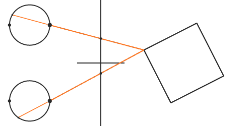
The projection can be done by drawing a line from each vertex of the object towards the pupil. The point where the line intersects the display corresponds with the pixel that should be lit. If light travelled in a straight line from the object, the light emitted from the display will continue in the same direction as the light that would have been reflected from the real-life object. When the light from the screen enters our eyes, our brain will trace back lines in the same fashion as before, and they will intersect at the exact location where the virtual object would have been, if it were real.
While the line-intersection metaphore is good for understanding the underlying principles, it is not what we use in a typical rendering application. A typical rasterization-based application uses projection matrices to project the geometry, as opposed to actually intersecting lines with the display. The reader may be familiar with projection matrices for mono rendering. In a stereo rendering setting, we need a different projection matrix for each eye. This is because the viewer's eyes are likely not centered at their respective halves of the screen. If they were, the projection matrix would be symmetric.

We obtain the projection matrix for one eye by creating a pyramid, defined by the four corners of that eye's screen half and the eye's distance from the screen. This becomes a frustum (a pyramid with the top chopped off) by specifying near and far clipping planes. Mathematically, the projection matrix can be written as
where the values of Right and Left depend on which eye the matrix is for. For the left eye, the values would be EyeIPD / 2 and -(ScreenWidth / 2 - EyeIPD / 2) respectively, as seen in the diagram above. The frustum will be vertically symmetric if the headset is built so the viewer sees an equal amount of the display when looking upwards as downwards. The usual projection procedures still apply, but the scene for the left eye must use its own projection matrix, different from the scene for the right eye.
As a small side note, the value of the near clipping plane does not need to coincide with the eye-to-display distance. The near and far clipping planes are only used for clipping geometry, while the eye-to-display distance must be exactly measured for the geometry to look correct to the viewer.
To render the stereoscopic scene, you will need to render the geometry as seen from the viewer's eyes. That is, you place two virtual cameras in the scene seperated by the distance between the viewer's eyes and rotated to match the orientation of the viewer's head. This will transform the coordinates of objects from world-space into view-space, where the eye is at the origin.
In the previous section, we assumed that the software knows the exact location of the viewer's pupils. The locations of the pupils then determine exactly the projection matrices and the necessary view-transformation matrices. Our brain will reproduce the correct image if the virtual cameras coincide with the location of the pupils. In this section we'll take a look at what happens when that is not the case. For example, let's say that the viewer's interpupillary distance (IPD) is slightly less than the population average of 64 millimetres.
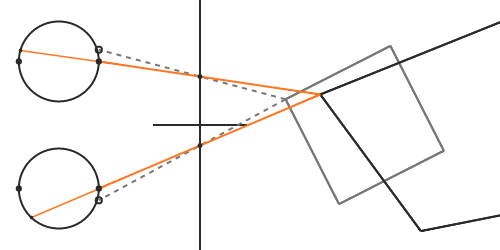
As in the previous section, we find the intersection point by drawing a line from the vertex of the object towards the virtual camera. But this time, the light emitted from the pixel towards our eyes does not continue in the same direction as the virtual light. When our brain traces this light back in the opposite direction, the intersection point will no longer be where the virtual object should be, and we perceive a distorted shape.
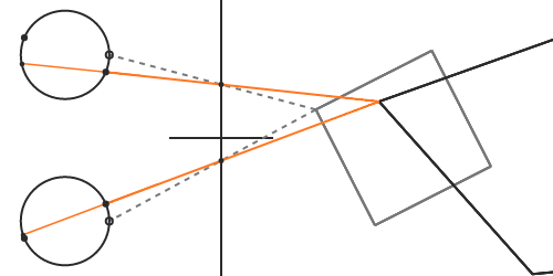
Unfortunately, even if knew the viewer's exact IPD, we would still have problems if the viewer's gaze is not straight forward - which happens if the viewer is focusing on a nearby object. In order to focus on objects closer to us, we naturally swivel our eyes inwards so that incoming light hits the high-resolution region of the fovea. This rotation of the eye will also cause a mismatch between the virtual camera position and the pupil.
The correct solution here requires eye tracking. Some headsets do install a pair of sensors that can detect the viewer's gaze at a high rate, but it is not yet commonplace for headsets in the market. Headsets without eye tracking will need to ensure that the viewer's focus is somewhat fixed or known, for instance by placing important content at a certain distance from the viewer. Alternatively, it is possible to reach approximate solutions [8] by placing the virtual cameras at the eye centres, as opposed to lying on the pupils.
While on the topic of focus, there is another important aspect to consider called accommodation [1]. The above-mentioned eye crossing is known as vergence [2], and deals with crossing the lines of sight at the focus point. This has the effect of merging objects seen by each eye into one object at the focus point. You can try this at home by focusing on your finger as you hold it close to your eyes. While doing this you will observe that objects in the distance appear to split into two.
Accommodation, the fact that the eyes' lenses have to change focal length based on the distance to observed objects, is a mechanism that works closely together with vergence. It has the effect of making objects that are out of focus appear blurry, while objects in focus remain sharp.
This is where we really start to run into problems with HMDs, since all light entering the eye will be coming from the same flat screen. In other words, all objects we perceive from the display will appear to be focused at the same distance. This leads to a conflict because our visual system is trained from early age to couple accommodation to vergence. Solving this problem is likely going to need good collaboration between hardware sensors and software post-processing [9].
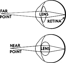
So far we have ignored the elephant in the room: You cannot possibly focus on a display that close to your face. That is why we need lenses. Unfortunately, introducing lenses also introduces a whole new set of issues to handle, such as chromatic aberration (color fringing), astigmatism (variation in focus), and geometric distortions where points on the image plane are shifted from where they would be without lenses.
First of all, our simple projection model breaks down. Even if our virtual cameras perfectly coincide with the viewer's pupils, the lenses will distort the light such that it no longer travels in a straight line. When our visual system traces rays back, it will do so assuming that they did go in a straight line, and they will intersect at a location different than where we intended. This mismatch causes us to perceive a distorted shape.
To understand how we can correct for this, we first need to understand what the lenses do - so that we can undo it. If one were to wear a HMD with lenses, and look at a 2D image of perfect vertical and horizontal lines, the user would perceive the following image:

The lines would bend inwards towards the centre of the image, producing what is known as a pincushion distortion [3]. The degree to which the lines bend depends on the optical properties of each lens.
This phenomenon is generally known as geometric lens distortion, and is most commonly corrected in software using an inverse distortion. After rendering the scene to each eye, the resulting image is distorted before it is presented on the display. When the distorted image is viewed through the lenses, the software distortion and the lens distortion will act against each other and the user will perceive straight lines.

The inverse of a pincushion distortion is called a barrel distortion, and has the effect of blowing lines radially outwards. A perfect inverse distortion would require knowledge of the exact optical properties of the lens. These properties are often unknown or simply not disclosed by the manufacturer, and we resort to a model of a handful of parameters that can be iteratively tweaked to give the best result for a specific lens.
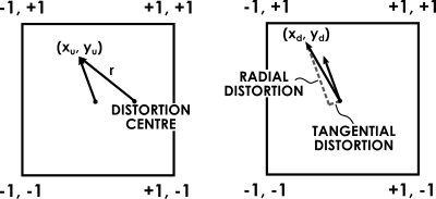
One such model is the Brown-Conrady model [4], and corrects for both radial and tangential distortion. Radial distortion causes image points that lie at the same radius from the centre to be translated equally. Tangential distortion, or decentering distortion, occurs at right angles to the radii. The latter must be taken into consideration when the viewer is not looking through the lens centre perfectly - i.e. when the viewer's IPD is not the same as the physical lens seperation in the HMD.
In the model, the coordinate of a point after distortion is found by adding a displacement to each component

where the displacement is

The radial distance from the distortion centre to the undistorted coordinate is denoted r, and the coefficients K1, K2, P1 and P2 are lens-specific parameters. The displacement is an infinite series, but a lower order approximation is often good enough for our purposes.
This distortion can be implemented as a post-processing effect using fragment shaders. After rendering the scene to an offscreen texture, we can run a fragment shader - one for each eye - over a quad that covers each eye's half of the display. The interpolated position inside the quad is transformed by applying the distortion and mapping the result to image coordinates.
In its simplest form the distortion shader would look like this:
There are some details that we have skipped over. One, the shader will need to scale the incoming coordinates to correct for aspect ratio. This is necessary since we want the distortion to be circular when presented on the display, but the quad might be stretched to be non-square depending on the size of the display. Furthermore, the distortion will also cause the image to shrink, wasting much of the available screen real-estate in the process. The latter can be corrected by rendering to a framebuffer of a higher resolution than the viewport it will be presented on, at the expense of performance.
Secondly, due to the lens being essentially like a prism, different wavelengths of light will get refracted by different amounts. This causes a phenomenon known as chromatic aberration, or color fringing, and gives a noticeable red or blue color fringe around objects. The effect grows stronger near the edges of the image, where the distortion is larger. To correct for this, we would need to distort each wavelength of light emitted from our display differently. This is rather difficult to do in software, so we approximate a solution by distorting the red, green and blue output channels seperately.
Lastly, the shader is not that efficient. We would like this step to take up as little of our rendering budget as possible. Recomputing the distortion factors - that are constant - for each pixel every frame is simply a waste of energy. A better solution is to precompute the radial and tangential distortion factors and store them in a texture. The above shader would then reduce to two texture lookups; one to find the distortion amount, and another to fetch the framebuffer texel.
Alternatively - this is done in the sample code - we could store the distorted texel coordinates themselves in the vertex attributes of a tessellated quad [5], to avoid the extra texture lookups. The coordinates would then be linearly interpolated between each vertex, and used directly in the fragment shader. This can give acceptable results, given a high enough resolution of the mesh, even though the distortion equations are nonlinear.
In this article we have covered the fundamentals of stereoscopic vision and the basics of stereoscopic rendering for a head-mounted display. We have looked at the importance of distortion correction, and how it can be performed efficiently as a post-processing effect.
There are many interesting topics we have not covered in this introductory article, such as
Many of these topics pose problems that have not been concerns in traditional 3D applications, but become crucial for comfortable VR experiences. Furthermore, to keep this introductory article simple, we have not discussed various other optimizations that can be done for VR rendering [5] where performance really matters.
[1] Wikipedia. "Accommodation", [available online]
[2] Wikipedia. "Vergence", [available online]
[3] Wikipedia. "Distortion (optics)", [available online]
[4] Wikipedia. "Distortion (optics), Software correction", [available online]
[5] Alex Vlachos. "Advanced VR Rendering", [available online]
[6] Jason P. de Villiers, et. al.. "Centi-pixel accurate real-time inverse distortion correction", [available online]
[7] Duane C. Brown. "Decentering Distortion of Lenses", [available online]
[8] Doc-Ok. "A Follow-up on Eye Tracking", [available online]
[9] Doc-Ok. "An Eye-tracked Oculus Rift", [available online]

