|
CMSIS-Driver Validation
Driver Validation
|

|
|
CMSIS-Driver Validation
Driver Validation
|
|
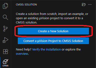
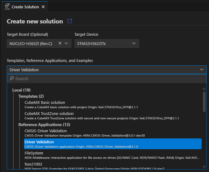
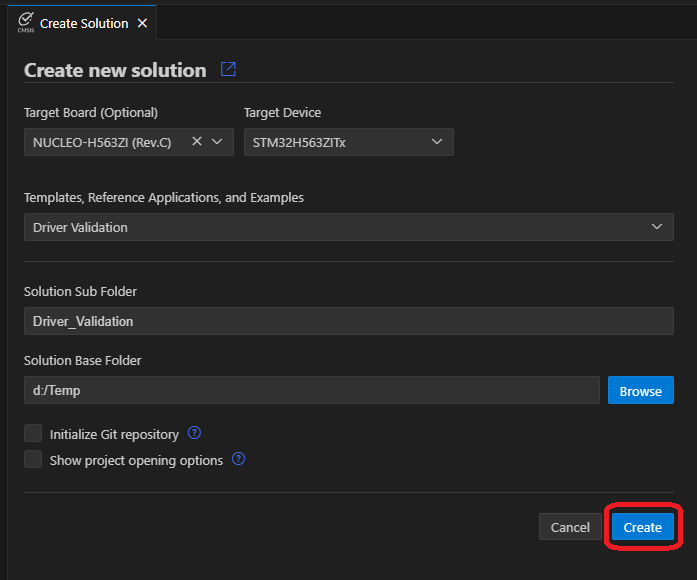
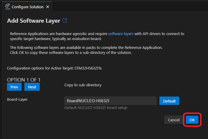
Using the Arm CMSIS Solution VS Code extension, create a new solution from template:
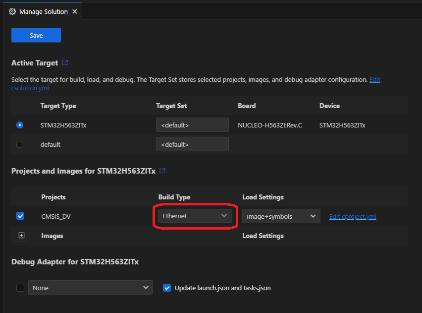
Note:
...in DV_..._Config.h file depends on the driver being validated; for example, for Ethernet, the file would be DV_ETH_Config.h file.
For validation configuration of specific driver check respective driver documentation:
For the interfaces that support loopback testing: Ethernet, USART and SPI, connect the following pins on your target hardware together (refer to the hardware schematics):
For the interfaces that support testing with dedicated server: WiFi, SPI and USART connect the related hardware as required by the related server:
Example below shows output results (in STDOUT channel) of an Ethernet driver testing :
CMSIS-Driver_Validation v3.1.0 CMSIS-Driver ETH Test Report   Oct  9 2025   07:30:34

TEST 01: ETH_MAC_GetVersion
  DV_ETH.c (267): [INFO] API version 2.2, Driver version 3.1
                                          PASSED
TEST 02: ETH_MAC_GetCapabilities          PASSED
TEST 03: ETH_MAC_Initialization           PASSED
TEST 04: ETH_MAC_PowerControl
  DV_ETH.c (366): [WARNING] Low power is not supported
                                          PASSED
TEST 05: ETH_MAC_MacAddress               PASSED
TEST 06: ETH_MAC_SetBusSpeed
  DV_ETH.c (445): [WARNING] Link speed 1G is not supported
                                          PASSED
TEST 07: ETH_MAC_Config_Mode              PASSED
TEST 08: ETH_MAC_Config_CommonParams      PASSED
TEST 09: ETH_MAC_Control_Filtering        PASSED
TEST 10: ETH_MAC_SetAddressFilter         PASSED
TEST 11: ETH_MAC_VLAN_Filter
  DV_ETH.c (910): [WARNING] Received non VLAN tagged frame
                                          PASSED
TEST 12: ETH_MAC_SignalEvent              PASSED
TEST 13: ETH_MAC_PTP_ControlTimer
  DV_ETH.c (1412): [WARNING] Precision Time Protocol is not supported
                                          NOT EXECUTED
TEST 14: ETH_MAC_CheckInvalidInit         PASSED
TEST 15: ETH_PHY_GetVersion
  DV_ETH.c (1018): [INFO] API version 2.2, Driver version 1.3
                                          PASSED
TEST 16: ETH_PHY_Initialization           PASSED
TEST 17: ETH_PHY_PowerControl
  DV_ETH.c (1114): [WARNING] Low power is not supported
  DV_ETH.c (1131): [WARNING] MAC is locked when PHY power is off
                                          PASSED
TEST 18: ETH_PHY_Config                   PASSED
TEST 19: ETH_PHY_CheckInvalidInit         PASSED
TEST 20: ETH_Loopback_Transfer            PASSED
TEST 21: ETH_Loopback_PTP
  DV_ETH.c (1574): [WARNING] Precision Time Protocol is not supported
                                          NOT EXECUTED
TEST 22: ETH_Loopback_External            PASSED

Test Summary: 22 Tests, 20 Passed, 0 Failed.
Test Result: PASSED