 |
OpenGL ES SDK for Android
ARM Developer Center
|
|
OpenGL ES SDK for Android
ARM Developer Center
|
Basic Normal Mapping tutorial that uses Normal Maps
One problem that comes up when doing mobile and indeed computer graphics is the balance between scene complexity and performance. To make a model look realistic it tends to need a vast amount of vertices and geometry. Unfortunately this can make the application run very slowly. Normal mapping is a method that allows a model to appear to have more complex geometry than in reality.
This works by combining simple geometry with the surface normals from a more complex version of the same geometry. First, we create the more complex geometry including the direction of all the surface normals. We then save these normals in a texture and apply them to your simple geometry to make it look more realistic. This tutorial will look at this technique.
This tutorial assumes you have read both and understood both the Texture Cube and Lighting examples. As you are going to be using techniques learned in both. You will need to load a normal map texture like in the texturing example and then light it using the techniques used in the lighting example.
When we were looking at the simple texture example we hard coded the texture into our source code. This was fine for our example as a 3 x 3 texture worked well to illustrate the point of the tutorial. In the real world textures are much bigger and you wouldn't want to include these directly in the source code. Especially if you are using quite a few textures.
One way around this is to include the textures as assets into the apk file itself. That way the texture will get compressed with the apk and will always be available. This is preferred over placing the file on the Android filesystem somewhere as it includes an extra step for the user to do.
Placing assets into an apk is very simple. If you notice in your project directory structure, there is a folder called assets. Any files that you place in this folder will be compressed into the apk when building. The problem is trying to get them out again. We must do this in the Java side so we need to modify NormalMapping.java
The first thing we need to do is add two new members to our class. One is a String to where we want to store our application data. We don't want to hard code this as in future Android versions this location may change. The second member is an instance of the android.content.Context. We need this to be able to access the AssetManager in order to get our files back out the apk.
In our onCreate method we need to set these two new members and do a call to a new extractAsset function which will extract our texture from the apk and place it in the application's data location on the device.
Our applicationContext is just initialised by calling the getApplicationContext function which is provided as a standard Android function. We then use it to see where we should store the applications files and store this in our string. After this we call our new extractAsset function with the name of the asset we want to extract. I think it is time we defined this function.
The idea of the function is simple, first check to see if the file we are trying to extract is on the filesystem. If it is then there is no further work needed as the file is already extracted. If not the function needs to continue and do some more work and extract it for us.
To extract our file to the filesystem we need to start by creating a file that will serve as the extracted version. We have chosen to use the RandomAccessFile class to do this. We then need to get an instance of the AssetManager this involves using the applicationContext that we defined earlier. Note we also need to do this in a try catch block as some of the functions that we are going to use with the files can throw exceptions.
We then read from the file and write to the output file using standard Java techniques. We use a InputStream to open the file in the AssetManager. Then we declare a buffer and fill it from the input stream. We then write that information out using the RandomAccessFile. Once this has finished we close both files and catch the exception that is all there is to it.
Now that we have extracted all our files from the asset manager it is time to edit our texture loading function to load textures from files instead of hardcoded values. First of all instead of defining an array that will be our texture we need to just define a pointer that we want to fill with the data.
The start of the function is exactly the same as the previous texture loading example. The only difference is when it comes to opening the file. Note how for now we have hardcoded the path for the texture. Ideally we would pass this in from the Java side as a JString but this is beyond the scope of this tutorial.
Once we have opened the file we then malloc some space for it. As we are opening a raw file the data is presented exactly the same way as the texture example. Red component followed by green and then finally by blue each a byte in size. Our texture is 256 x 256 so we need to times this value by 3 because each pixel has 3 components. If you are using your own texture with different dimensions you need to edit this line.
We then read the texture into the space we just allocated again only reading 256 x 256 x 3 bytes. We then feed this information into glTexImage2D as before, and then we need to free the space that we allocated earlier as the texture will have been copied into the GPU.
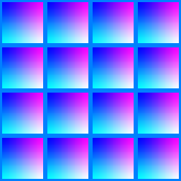
As mentioned earlier we are going to increase the detail and complexity of our scene by using a normal map. A normal map is a regular texture but instead of defining what colour a pixel will be on screen, it determines what the surface normal will be for each pixel. The red, green and blue channels in the texture tell you the X, Y and Z components of the normal direction respectively.
To understand this better it's a good idea to look at the texture that is provided with this tutorial. Open the image with your favourite image editing software, so you can look at the colours and see what the colour components are at each pixel. For our example we have always left the Z coordinate to be fully on. The texture image has been provided below for your convenience.
Note the bump mapping technique is really similar to this, the only difference is that a bump map texture is defined only in one channel. This then tells you a height value of a particular point in the map. With this you can then do some calculations in your fragment shader to achieve some really nice effects.
The only difficulty with using a normal map is it doesn't take into account the rotation of the object. In the lighting example we translated our normals by the model view matrix but we can't do this if we are loading from a texture. This presents a problem.
One solution to this problem is to move the eye vector and the light vector into something called the tangent space. A space can be defined with three axes that are orthogonal to each other. The tangent space is the space that has two axes on the face you are trying to render and the third coming out of the face. The axes coming out of the face is called the normal that we have previously discussed. Either one of the two remaining is known as the tangent and the one left is called the biNormal. This is a complicated concept and there are two ways that may help you understand:
Now in our example we have defined the tangent and biNormal seperately. This is done to aid understanding of the concepts involved it is quite possible to work out the biNormal by using something called the cross product. If you prefer to do this don't pass the biNormal in as a parameter and add the appropriate line in your shader. More on this when we discuss the changes to the shader.
The vertices are just the same as they were in the Simple Cube or the Texture Cube example. 4 defined per face to generate a familiar cube. The normals are also defined so they are 4 per face. Unlike the lighting example they are all the same and all point perpendicular to the face. So the top face has 4 pointing in the positive Y direction. The back face has 4 pointing in the negative Z direction and so on.
Next are the colours; these are taken directly from the simple cube example and define a solid colour for each of the faces. After that is our first completely new section which is the tangents to each of the faces. Like the normals, 4 are defined per face and they are all the same. For the front face this is in the positive X direction, which as mentioned before, lies in the plane of the face and is perpendicular to the normal which is defined in positive Z direction. Keeping this in mind, the back face has a tangent in the negative X direction, the right and left faces have one in the negative Z and positive Z in respectively. The top and bottom are trickier and are both defined to have a tangent in the positive X direction.
To finish our space off we need to define the biNormal. This has to be perpendicular to both the normal and the tangent. Now for the front, back, right and left faces this can just be the positive Y direction. The top and bottom can�t do this unfortunately as their normal is the positive y and negative y axes respectively. This means we need to select the positive x direction instead to produce the same axes in the same orientation as the other sides. Again use the methods mentioned above if you need to solidify your understanding.
One extra thing to note is that there is a link between the texture coordinates that we have defined, and the way we have defined our axes. If we get this wrong then the texture can be displayed upside down, or the lighting can appear to be incorrect. This is also true for the texture example. However, as we didn't use normals or tangents in that example this was skipped past as it wasn't relevant at the time.
Finally the texture coordinates are defined to be the same as the texture coordinates in the TextureCube example.
The vertex shader looks simpler than the vertex shader in the Lighting tutorial. This is due to the fact that a lot of the calculations have been moved to the fragment shader. The first line in the main function creates a temporary variable that is equal to the current vertex that has been transformed by the modelView matrix. This is needed when working out the eye vector from the current vertex.
The next line transforms the vertex normal in much the same way you did in the lighting tutorial. Although all the complex normals we are going to use are defined in our normal map we still need to use the "real" vertex normal to create the matrix that will move our light and eye vectors into the tangent space.
The next two lines define our inverseLightDirection and inverseEyeDirection. The inverseLightDirection uses the same code as the Lighting tutorial. As we are still only dealing with directional light we don't need to get a vector from the vertex to the light as all light is treated as being parallel direction vectors.
The three lines after this should be pretty simple stuff for us now. They set gl_Position to be exactly the same as numerous other tutorials and pass the texture coordinates and colours through to the fragment shader without being touched. After these lines we define the transformedTangent and the transformedBinormal. Remember how I said that we needed 3 things to convert our eye and light vectors into tangent space? Well we already have the normal so next we need to take the passed in both the tangent and biNormal and transform it by the modelview matrix.
Note if you want to work out the biNormal by using the cross product you should do the line here. So after transformedTangent you should write:
Then pass this in as a parameter to the tangent matrix. Note, the cross product function is built into OpenGL ES 2.0.
The final 3 lines of the vertex shader are responsible for converting the eyeVector and lightVector into tangent space. First we need to create a new transformation matrix this is made up of the tangent, bi normal and normal vectors we have created earlier. We then simply multiply the light and the eye by this new matrix in turn. That's all there is to it!!
The fragment shader should look very familiar as much of the code came from the vertex shader of the Lighting tutorial. The first line of the main function sets the starting fragment colour and sets it to black or an absence of both light and colour.
The next two lines just get the normal from the normal map texture in much the same way we got a colour from a regular texture in the Lighting example. From then on everything is near enough identical to the Lighting example. The diffuse is worked out and added to the frag colour, then the ambient and finally the specular light. This is then clamped to between 0.0 and 1.0 and is used to set gl_FragColor.
We are almost finished with our new Normal mapping example. We just need to tie the new attributes and uniforms in the shader with actual values from the main program.
Above is a list of all the location variables you will need to make this tutorial work. Starting with the vertexLocation which will store the location of the vertex attribute and finishing with our new tangentLocation which will store the location of our tangents. The code to set these locations to the correct values is presented below.
Finally here is the code to supply the locations above with their corresponding data. This should almost be coming second nature to you now.
That is all there is to it go and enjoy your lovely normal mapped cube.

