OpenGL ES SDK for Android ARM Developer Center
 All Classes Namespaces Files Functions Variables Typedefs Enumerations Enumerator Friends Macros Pages
Occlusion Query

Demonstration of Occlusion Query functionality in OpenGL ES 3.0.

Introduction

It's assumed that you have read and understood all of the mechanisms described in Asset Loading,Simple Triangle and Texture Cube.

Overview

OcclusionQuery_android.png
We are rendering a horizontally located plane, on top of which we lay some rounded cubes.

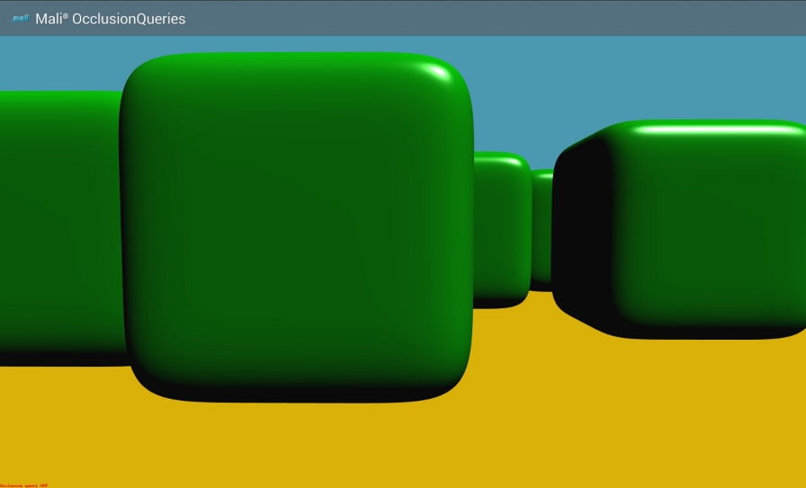
The main purpose of the application is to show the difference in performance when the occlusion query mode is on or off. If the occlusion query mode is on, then only the cubes that are visible to the viewer are rendered. In the other case, when the occlusion query mode is off, then all of the cubes are rendered, which leads to a massive decrease in performance.

  • In the case where occlusion query mode in on: if there is a small number of objects visible for a viewer, the application runs very smooth; the larger the number of the visible objects, the slower the animation is, but still the performance is better than in the following case.
  • In the case where occlusion query mode in off: the performance is constant (very low), regardless of the number of visible cubes (all of them are always rendered).

We are rendering rounded cubes - the objects are more complicated than the normal cubes, which means the time needed for rendering this kind of objects is longer. We are using this fact to demonstrate the occlusion query mode. When we want to verify whether the object is visible for a viewer, we can draw a simpler object (located in the same position as the requested one and being almost of the same size and shape), and once we get the results, we are able to render only those rounded cubes which passed the test.

There is also text displayed (at the bottom left corner of the screen) showing whether the occlusion query mode is currently on or off. The mode changes every 10 seconds.

Render a Geometry

In the application we are rendering a plane, cubes and rounded cubes. The "normal" cubes are rendered only in occlusion query mode to verify whether the object is visible for a viewer, but they are not visible on the screen: more detail is provided in the following section Occlusion Queries.

The first step we should take is to generate the coordinates of the objects we would like to render and prepare them for the draw calls. Let's describe the mechanism based on an example of a plane object as all of the objects should be prepared in the same way.

We want to draw a plane which is laid horizontally, which in the 3D space means it should be located in XZ space. Please note that there will also be lighting applied, which means that we will need normals as well.

OcclusionQueriesGeometry_plane.png
Schema presenting plane vertices in XZ space.

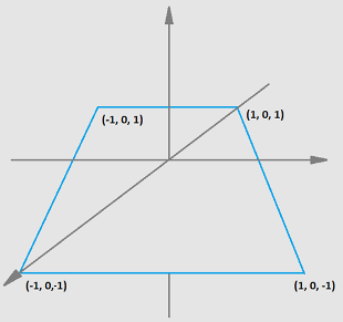
The basic OpenGL ES rendering technique is based on drawing triangles that make up a requested shape. This will be our next step. It's important to mention here that whilst describing plane triangle vertices, you should follow the clockwise or counter-clockwise order, otherwise OpenGL ES will have trouble in detecting the front and back faces. In this example we are using clockwise (CW) order to describe plane coordinates as this is the default for OpenGL ES.

PlaneModel::getTriangleRepresentation(&numberOfPlaneVertices,
void PlaneModel::getTriangleRepresentation(int* numberOfPoints, int* numberOfCoordinates, float** coordinates)
{
/* Example:
* z D __________ C
* . | / |
* / \ | / |
* | | / |
* | |/_________|
* | A B
* |----------> x
*/
ASSERT(coordinates != NULL, "Cannot use null pointer while calculating coordinates.");
/* Define point coordinates. */
const Vec4f pointA = {-1.0f, 0.0f, -1.0f, 1.0f};
const Vec4f pointB = { 1.0f, 0.0f, -1.0f, 1.0f};
const Vec4f pointC = { 1.0f, 0.0f, 1.0f, 1.0f};
const Vec4f pointD = {-1.0f, 0.0f, 1.0f, 1.0f};
/* 2 triangles, 3 points of triangle, 4 coordinates for each point. */
const int numberOfSquarePoints = numberOfSquareTriangles *
numberOfTrianglePoints;
const int numberOfSquareCoordinates = numberOfSquarePoints *
numberOfPointCoordinates;
/* Allocate memory for result array. */
*coordinates = (float*) malloc (numberOfSquareCoordinates * sizeof(float));
/* Is allocation successful? */
ASSERT(*coordinates != NULL, "Could not allocate memory for result array.");
/* Index of an array we will put new point coordinates at. */
int currentIndex = 0;
/* First triangle. */
/* A */
(*coordinates)[currentIndex++] = pointA.x;
(*coordinates)[currentIndex++] = pointA.y;
(*coordinates)[currentIndex++] = pointA.z;
(*coordinates)[currentIndex++] = pointA.w;
/* B */
(*coordinates)[currentIndex++] = pointB.x;
(*coordinates)[currentIndex++] = pointB.y;
(*coordinates)[currentIndex++] = pointB.z;
(*coordinates)[currentIndex++] = pointB.w;
/* C */
(*coordinates)[currentIndex++] = pointC.x;
(*coordinates)[currentIndex++] = pointC.y;
(*coordinates)[currentIndex++] = pointC.z;
(*coordinates)[currentIndex++] = pointC.w;
/* Second triangle. */
/* A */
(*coordinates)[currentIndex++] = pointA.x;
(*coordinates)[currentIndex++] = pointA.y;
(*coordinates)[currentIndex++] = pointA.z;
(*coordinates)[currentIndex++] = pointA.w;
/* C */
(*coordinates)[currentIndex++] = pointC.x;
(*coordinates)[currentIndex++] = pointC.y;
(*coordinates)[currentIndex++] = pointC.z;
(*coordinates)[currentIndex++] = pointC.w;
/* D */
(*coordinates)[currentIndex++] = pointD.x;
(*coordinates)[currentIndex++] = pointD.y;
(*coordinates)[currentIndex++] = pointD.z;
(*coordinates)[currentIndex++] = pointD.w;
if (numberOfPoints != NULL)
{
*numberOfPoints = numberOfSquarePoints;
}
if (numberOfCoordinates != NULL)
{
*numberOfCoordinates = numberOfSquareCoordinates;
}
}

We will need plane normals as well.

PlaneModel::getNormals(&sizeOfPlaneNormalsArray,
void PlaneModel::getNormals(int* numberOfCoordinates, float** normals)
{
ASSERT(normals != NULL, "Cannot use null pointer while calculating coordinates.");
/* 2 triangles, 3 points of triangle, 3 coordinates for each point. */
const int numberOfNormalsCoordinates = numberOfSquareTriangles *
numberOfTrianglePoints *
numberOfPointCoordinates;
/* Index of an array we will put new point coordinates at. */
int currentIndex = 0;
/* Allocate memory for result array. */
*normals = (float*) malloc (numberOfNormalsCoordinates * sizeof(float));
/* Is allocation successful? */
ASSERT(*normals != NULL, "Could not allocate memory for result array.");
for (int i = 0; i < numberOfNormalsCoordinates; i += numberOfPointCoordinates)
{
(*normals)[currentIndex++] = 0.0f;
(*normals)[currentIndex++] = 1.0f;
(*normals)[currentIndex++] = 0.0f;
(*normals)[currentIndex++] = 1.0f;
}
if (numberOfCoordinates != NULL)
{
*numberOfCoordinates = numberOfNormalsCoordinates;
}
}

Once we have generated the plane coordinates we should focus on the API. We need buffer objects to store the generated data. But we will need Vertex Array objects as well to easily determine which vertex data (stored in buffer objects) should be used for a specific draw command. As written in the OpenGL ES 3.0 documentation: The buffer objects that are to be used by the vertex stage of the GL are collected together to form a vertex array object. To generate Vertex Array object we need to call

GL_CHECK(glGenVertexArrays(1, &planeVertexArrayObjectId));

As mentioned before, we will need buffer objects to store generated data. To create ones we need to issue

GL_CHECK(glGenBuffers(1, &planeVerticesBufferId));

What we need to do now is to copy plane coordinates and plane normals to the specific buffer objects.

GL_CHECK(glBindBuffer (GL_ARRAY_BUFFER,
GL_CHECK(glBufferData (GL_ARRAY_BUFFER,
GL_STATIC_DRAW));
GL_CHECK(glBindBuffer (GL_ARRAY_BUFFER,
GL_CHECK(glBufferData (GL_ARRAY_BUFFER,
sizeOfPlaneNormalsArray * sizeof(float),
GL_STATIC_DRAW));

To define an array of generic vertex attribute data, we need to call

GL_CHECK(glVertexAttribPointer(verticesAttributeLocation,
4,
GL_FLOAT,
GL_FALSE,
0,
0));
GL_CHECK(glVertexAttribPointer(normalAttributeLocation,
4,
GL_FLOAT,
GL_FALSE,
0,
0));

Please note that these commands should be called for a specific buffer object being currently bound, which means the call hierarchy should look like follows

GL_CHECK(glBindBuffer (GL_ARRAY_BUFFER,
GL_CHECK(glBufferData (GL_ARRAY_BUFFER,
GL_STATIC_DRAW));
GL_CHECK(glVertexAttribPointer(verticesAttributeLocation,
4,
GL_FLOAT,
GL_FALSE,
0,
0));
GL_CHECK(glBindBuffer (GL_ARRAY_BUFFER,
GL_CHECK(glBufferData (GL_ARRAY_BUFFER,
sizeOfPlaneNormalsArray * sizeof(float),
GL_STATIC_DRAW));
GL_CHECK(glVertexAttribPointer(normalAttributeLocation,
4,
GL_FLOAT,
GL_FALSE,
0,
0));

In the glVertexAttribPointer() calls we use verticesAttributeLocation and normalAttributeLocation as arguments. These values indicate the locations of the attributes within a program object that are used for rendering the specific geometry. We will describe the problem in more details at the end of this section.

The next step is to bind vertex array object

GL_CHECK(glBindVertexArray(planeVertexArrayObjectId));

and enable vertex attrib arrays

GL_CHECK(glEnableVertexAttribArray(verticesAttributeLocation));
GL_CHECK(glEnableVertexAttribArray(normalAttributeLocation));

When we want to render the plane, we need to make sure that the specific vertex array object is currently bound and then issue the draw call.

{
GL_CHECK(glBindVertexArray (planeVertexArrayObjectId));
1,
1,
GL_FALSE,
planeNormalMatrix.getAsArray()));
1,
GL_FALSE,
planeWorldInverseMatrix.getAsArray()));
GL_CHECK(glUniformMatrix4fv(mvpMatrixUniformLocation,
1,
GL_FALSE,
planeMvpMatrix.getAsArray()));
GL_CHECK(glDrawArrays (GL_TRIANGLES,
0,
}

At this point, the reader should be already aware of how to prepare and use program objects. Let us briefly describe the mechanism.

  1. Create program object:
    programId = GL_CHECK(glCreateProgram());
  2. Create shader object:
    *shaderObjectIdPtr = GL_CHECK(glCreateShader(shaderType));
  3. Set shader source:
    GL_CHECK(glShaderSource(*shaderObjectIdPtr, 1, strings, NULL));
    Please note that the strings variable is storing the shader source read from a file.
    strings[0] = loadShader(filename);
  4. Compile shader:
    GL_CHECK(glCompileShader(*shaderObjectIdPtr));
    It's always a good idea to check whether compilation succeeded by checking GL_COMPILE_STATUS (GL_TRUE is expected).
    GL_CHECK(glGetShaderiv(*shaderObjectIdPtr, GL_COMPILE_STATUS, &compileStatus));

Once you have called the functions for both fragment and vertex shaders, you should now attach both to a program object,

GL_CHECK(glAttachShader(programId, vertexShaderId));
GL_CHECK(glAttachShader(programId, fragmentShaderId));

link the program object,

GL_CHECK(glLinkProgram(programId));

and set the program object to be used (active).

GL_CHECK(glUseProgram (programId));

The verticesAttributeLocation and normalAttributeLocation arguments used in the glVertexAttribPointer() calls are attrib locations which are retrieved with the following call.

GLuint normalAttributeLocation = GL_CHECK(glGetAttribLocation (programId, "normal"));
GLuint verticesAttributeLocation = GL_CHECK(glGetAttribLocation (programId, "vertex"));

The second argument corresponds to the attribute name used in the vertex shader.

Vertex shader code

/* Vertex and normal vector attributes sent from the program. */
in vec4 vertex;
in vec4 normal;
/* This matrix is used to set the perspective up and is sent from the program. */
/* This matrix is used to set the view up and is sent from the program. */
uniform mat4 normalMatrix;
uniform mat4 mvpMatrix;
/* Output normal vector (used to compute light). */
out vec3 normalOut;
/* Vertex position in world space that we pass to fragment shader. */
out vec4 modelPosition;
/* Inverted model-view-projection matrix passed to the fragment shader to compute light. */
out mat4 worldInverse;
void main()
{
/* Calculate normal vector in world space (used to calculate light). */
normalOut = vec3(normalMatrix * normal);
modelPosition = modelMatrix * vertex;
gl_Position = mvpMatrix * vertex;
}

Fragment shader code

precision highp float;
/* These values are passed to the fragment shader from the vertex shader. */
in vec3 normalOut;
in vec4 modelPosition;
/* Color of a geometry. */
uniform vec4 color;
/* Inverted model-view-projection matrix that will be used to compute light. */
uniform mat4 worldInverseMatrix;
/* Output object's color. */
out vec4 outColor;
/* Structure that describes the light source. */
struct lightSource
{
vec4 position;
vec4 diffuse;
vec4 specular;
};
/* Structure that describes material. */
struct material
{
vec4 ambient;
vec4 diffuse;
vec4 specular;
float shininess;
};
void main()
{
/* Ambient light factor. */
vec4 sceneAmbient = vec4(0.2, 0.2, 0.2, 1.0);
/* Light source with hard coded parameters. */
lightSource light = lightSource(vec4(50.0, 100.0, 50.0, 0.0),
vec4( 1.0, 1.0, 1.0, 1.0),
vec4( 1.0, 1.0, 1.0, 1.0));
/* New material with hard coded parameters. */
material frontMaterial = material(vec4(0.2, 0.2, 0.2, 1.0),
color,
vec4(1.0, 1.0, 1.0, 1.0),
25.0);
/* Set vectors up. */
vec3 normalDirection = normalize(normalOut);
/* We need a direction to the viewer. That's why we compute difference between the camera position (worldInverseMatrix) and vertex position (modelPosition). */
vec3 viewDirection = normalize(vec3(worldInverseMatrix * vec4(0.0, 0.0, 0.0, 1.0) - modelPosition));
vec3 lightDirection;
float attenuation;
/* Check if it's a directional light. */
if (0.0 == light.position.w)
{
/* No attenuation. */
attenuation = 1.0;
/* Setup light direction. */
lightDirection = normalize(vec3(light.position));
}
/* Compute ambient factor of the light. It's done by multiplying sceneAmbient color and material ambient color. */
vec3 ambientLighting = vec3(sceneAmbient) * vec3(frontMaterial.ambient);
/* Compute diffuse reflection. Diffuse reflection = attenuation * lightDiffuse * materialDiffuse * (normalDirection o lightDirection). */
vec3 diffuseReflection = attenuation *
vec3(light.diffuse) *
vec3(frontMaterial.diffuse) *
clamp(dot(normalDirection, lightDirection), 0.0, 1.0);
/* Check if the light source is on the proper side. */
vec3 specularReflection = vec3(0.0, 0.0, 0.0);
if (dot(normalDirection, lightDirection) >= 0.0)
{
/* If it's on the right side, compute specularReflection. Specular reflection = attenuation * lightSpecular * materialSpecular * (-lightDirection o normalDirection). */
specularReflection = attenuation *
vec3(light.specular) *
vec3(frontMaterial.specular) *
pow(max(0.0, dot(reflect(-lightDirection, normalDirection), viewDirection)), frontMaterial.shininess);
}
/* Set the final color of the object. */
outColor = vec4(ambientLighting + diffuseReflection + specularReflection, 1.0);
}

Occlusion Queries

As already mentioned before, the main purpose of the application is to show the difference in the performance when the occlusion query mode is on or off. The occlusion query mechanism is used to verify whether an object is visible for a viewer or if it is occluded by other objects (in this case there is no need to render it as we are not able to see it anyway). If all of the objects which are not visible are ignored, then the application runs much faster in comparison to rendering all of the objects. This is where we are able to use an optimization trick. We want to render rounded cubes on a screen, which is rather a complicated geometry and rendering it takes some time. But we can use a very similar shape, that is much easier to render: the normal cube, only to verify the occlusion. But let us describe the problem in details.

First of all, we need to generate the query objects.

When we want the occlusion query mode to be issued, we are render the normal cubes as well, so we need to set a proper vertex array object to be active.

We don't want the normal cubes to be visible on screen, this is why we are calling

GL_CHECK(glColorMask(GL_FALSE, GL_FALSE, GL_FALSE, GL_FALSE));

Then we can enable the query test and render each cube (separately).

for (int i = 0; i < NUMBER_OF_CUBES; i++)
{
/* Begin occlusion query. */
GL_CHECK(glBeginQuery(GL_ANY_SAMPLES_PASSED, cubeQuery[i]));
{
GL_CHECK(glDrawArrays(GL_TRIANGLES, 0, numberOfCubeVertices));
}
GL_CHECK(glEndQuery(GL_ANY_SAMPLES_PASSED));
/* End occlusion query. */
}

Then we restore the color mask, so that the next draw call results will be visible on screen.

/* Clear depth buffer and enable color mask to make rounded cubes visible. */
GL_CHECK(glColorMask(GL_TRUE, GL_TRUE, GL_TRUE, GL_TRUE));

We would like to draw the rounded cubes now, so the proper vertex array object should be used.

/* Draw rounded cubes. */

Now, for each cube, we need to verify whether it should be rendered or not. We need to get the query result.

GL_CHECK(glGetQueryObjectuiv(cubeQuery[i], GL_QUERY_RESULT, &queryResult));

And in case, the GL_TRUE is returned (which means the cube is visible), we can issue the draw call

GL_CHECK(glDrawArrays(GL_TRIANGLES,
0,

In the application, we are doing one more thing to make the occlusion test work properly. We are sorting the cubes' positions from the nearest to the furthest (relative to the viewer's position). This should be issued before the occlusion test.

/* Sort the cubes' positions. We have to do it in every frame because camera constantly moves around the scene.
* It is important that the cubes are rendered front to back because the occlusion test is done per draw call.
* If the cubes are draw out of order then some cubes may pass the occlusion test even when they end up being
* occluded by geometry drawn later. */

If we now would want to turn off the occlusion query mode, we should just simply render all of the rounded cubes.

/* Draw all rounded cubes without using occlusion queries. */
for(int i = 0; i < NUMBER_OF_CUBES; i++)
{
GL_CHECK(glDrawArrays(GL_TRIANGLES,
0,
}