This section gives an overview of the general operation of CMSIS-Drivers. It explains the Common Driver Functions that are common in all CMSIS-Drivers along with the Function Call Sequence. The topic Data Transfer Functions describes how data read/write operations to the peripheral are implemented.
Each CMSIS-Driver defines an Access Struct for calling the various driver functions and each peripheral (that is accessed via a CMSIS-Driver) has one Driver Instance.
Each CMSIS-Driver contains these functions:
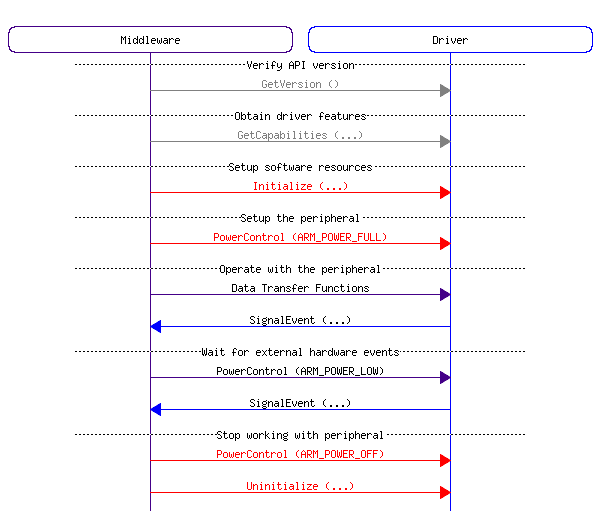
GetVersion: can be called at any time to obtain version information of the driver interface.GetCapabilities: can be called at any time to obtain capabilities of the driver interface.Initialize: must be called before powering the peripheral using PowerControl. This function performs the following:SignalEvent callback function.SignalEvent: is an optional callback function that is registered with the Initialize function. This callback function is initiated from interrupt service routines and indicates hardware events or the completion of a data block transfer operation.PowerControl: Controls the power profile of the peripheral and needs to be called after Initialize. Typically, three power options are available (see ARM_POWER_STATE):ARM_POWER_FULL: Peripheral is turned on and fully operational. The driver initializes the peripheral registers, interrupts, and (optionally) DMA.ARM_POWER_LOW : (optional) Peripheral is in low power mode and partially operational; usually, it can detect external events and wake-up.ARM_POWER_OFF: Peripheral is turned off and not operational (pending operations are terminated). This is the state after device reset.Uninitialize: Complementary function to Initialize. Releases the I/O pin resources used by the interface.Control: Several drivers provide a control function to configure communication parameters or execute miscellaneous control functions.The section Function Call Sequence contains more information on the operation of each function. Additional functions are specific to each driver interface and are described in the individual sections of each driver.
The CMSIS-Driver functions access peripherals and interrupts and are designed to execute in Privileged mode. When calling CMSIS-Driver functions from RTOS threads, it should be ensure that these threads execute in Privileged mode.
For normal operation of the driver, the API functions GetVersion, GetCapabilities, Initialize, PowerControl, Uninitialize are called in the following order:

The functions GetVersion and GetCapabilities can be called any time to obtain the required information from the driver. These functions return always the same information.
To start working with a peripheral the functions Initialize and PowerControl need to be called in this order:
Initialize typically allocates the I/O resources (pins) for the peripheral. The function can be called multiple times; if the I/O resources are already initialized it performs no operation and just returns with ARM_DRIVER_OK.PowerControl (ARM_POWER_FULL) sets the peripheral registers including interrupt (NVIC) and optionally DMA. The function can be called multiple times; if the registers are already set it performs no operation and just returns with ARM_DRIVER_OK.To stop working with a peripheral the functions PowerControl and Uninitialize need to be called in this order:
The functions PowerControl and Uninitialize always execute and can be used to put the peripheral into a Safe State, for example after any data transmission errors. To restart the peripheral in a error condition, you should first execute the Stop Sequence and then the Start Sequence.
PowerControl (ARM_POWER_OFF) terminates any pending data transfers with the peripheral, disables the peripheral and leaves it in a defined mode (typically the reset state).Uninitialize always releases I/O pin resources.All CMSIS-Driver provide a Start Sequence and Stop Sequence. Therefore two different drivers can share the same I/O pins, for example UART1 and SPI1 can have overlapping I/O pins. In this case the communication channels can be used as shown below:
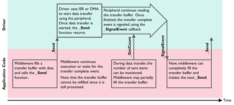
A CMSIS-Driver implements non-blocking functions to transfer data to a peripheral. This means that the driver configures the read or write access to the peripheral and instantly returns to the calling application. The function names for data transfer end with:
Send to write data to a peripheral.Receive to read data from a peripheral.Transfer to indicate combined read/write operations to a peripheral.During a data transfer, the application can query the number of transferred data items using functions named GetxxxCount. On completion of a data transfer, the driver calls a callback function with a specific event code.
During the data exchange with the peripheral, the application can decide to:
The following diagram shows the basic communication flow when using the _Send function in an application.

A CMSIS-Driver publishes an Access Struct with the data type name ARM_DRIVER_xxxx that gives to access the driver functions.
Code Example: Function Access of the SPI driver
A device may offer several peripherals of the same type. For such devices, the CMSIS-Driver publishes multiple instances of the Access Struct. The name of each driver instance reflects the names of the peripheral available in the device.
Code Example: Access Struct for three SPIs in a microcontroller device.
The access functions can be passed to middleware to specify the driver instance that the middleware should use for communication.
Naming Convention
The access structs need to follow this naming convention: the keyword Driver followed by an underscore _, the interface name IFNAME (usually in upper case letters), and the instance number n. Here's the full list of access struct names for all drivers (n to be replaced with the actual instance number):
Example:
The API of each CMSIS-Driver peripheral is published in a corresponding header file in the directory .\CMSIS\Driver\Include\ It is recommended to include such header file in the implementation file of the CMSIS-Driver.
Template files are available to simplify the development of a CMSIS-Driver. These are code skeletons that provide the structure of a CMSIS-Driver. They are available in the directory.\CMSIS\Driver\DriverTemplates\. You can also refer to working CMSIS-Driver Implementations to see how CMSIS-Drivers get implemented on real devices.
The table below summarizes the API header and template files for CMSIS-Driver interfaces, with links to GitHub and API references.
For a device family, the drivers may be configurable, but the configuration of the drivers itself is not part of the CMSIS-Driver specification.
The following example code shows the usage of the SPI interface.