USB Component  
MDK Middleware for USB Device and Host Communication
 
Loading...
Searching...
No Matches
USB Host

This chapter describes the software structure of the USB Host Component and explains its use for creating an USB Host application.

The USB Host Component simplifies software development of microcontroller systems that allow to connect USB Devices. The attributes of the USB Host Component are:

  • Complies with the USB 2.0 specification.
  • Support for HID, MSC, CDC, and Custom USB Device Classes to be connected to the USB Host.
  • Support for control, interrupt and bulk transfer types.

RTE Components

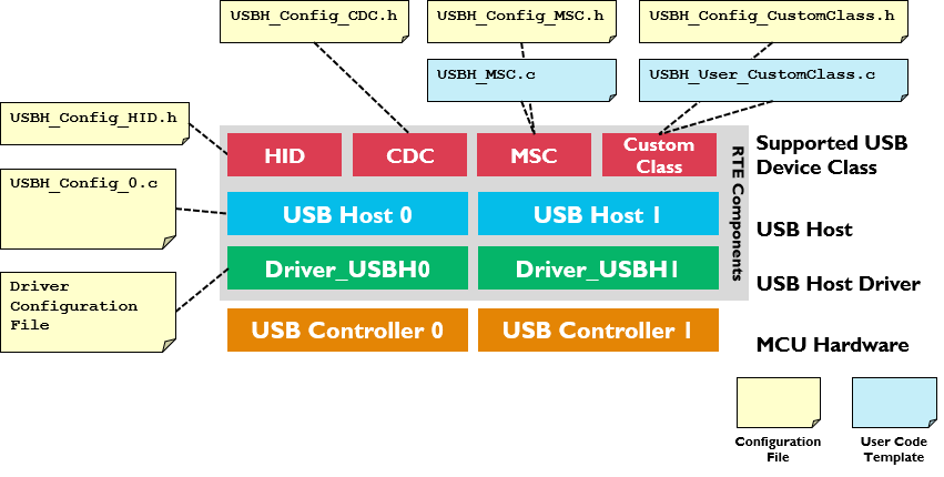
The following picture shows the relationships of the RTE Components with the microcontroller's USB Host peripheral (USB Controller). RTE Components provide configuration files and user code templates. Configuration files configure the RTE Components, hardware interfaces, memory resources and USB Host parameters. User code templates provide the skeleton for implementing support for different USB Device classes.

USB Host Structure

Create an Application

The steps to create a microcontroller application that functions as an USB Host are:

  1. Select RTE Components that are required for your application.
  2. Enable and configure the USB Host Driver.
  3. Configure the USB Host that connects the USB Middleware to the microcontroller USB peripheral.
  4. Configure the System Resources according to the USB Host component's Resource Requirements.
  5. Configure the parameters of the attached USB Devices.
  6. Implement the Application Code using code templates that are provided to support various USB Device Classes.
  7. Debug you application using the built-in mechanisms of the USB Component.

RTE Component Selection

The RTE Component selection is done in a few steps:

  1. From the USB Component:
    • Select USB:CORE that provides the basic functionality required for USB communication.
    • Set USB:Host to '1'. This creates one USB Host for communication with attached USB Devices.
    • Select the desired support for USB Classes (HID/MSC/CDC/Custom Class). For example, select USB:Host:HID to support HID Class Devices only.
  2. From the Drivers Component:
    • Select an appropriate USB Host driver suitable for your application.
  3. From the Device Component:
    • Additional device specific drivers may be required according to the validation output.
  4. From the CMSIS Component:
    • Select the CMSIS:CORE to provide the core interface to the processor.
    • Select a suitable CMSIS:RTOS2 that is a required for the application.
RTE Component Selection

USB Driver and Controller

The USB Host Driver and the USB Controller of the microcontroller need to be correctly configured. In particular this means:

  • The USB Host Driver selected under the Drivers Component is typically configured with a driver specific configuration header file. Some microcontrollers may require settings that related to a physical layer interface (PHY), the USB VBUS power and Overcurrent protection.
  • The USB Controller of the microcontroller needs typically specific clock settings. Consult the user's guide of the microcontroller to understand the requirements. Alternatively you may copy the setup of an USB Host example that is provided for various evaluation boards.

USB Host Configuration

The USBH_Config_n.h file contains additional settings for the specific USB Host:

  • The Driver_USBH# is set according to the selected USB Controller. For device with single USB Host Controller it will typically be '0'.
  • Power Consumption can be configured according to hardware capability of the USB Host Controller.
  • Maximum Pipes can be specified according to expected USB Device classes that are expected to be used by the USB Host.
  • Memory Pool parameters can be configured that are necessary for USB Host operation. This memory pool can also be located to specific memory via the linker script.

Refer to Configuration for a detailed list of all available settings.

System Resource Configuration

For proper operation, the USB Host Component requires some system configuration settings. The requirements are:

  • Additional main stack size of 512 bytes.
  • The USB Host Component uses CMSIS-RTOS2 threads. In case RTX v5 is used no changes to RTX settings are necessary as all resources are allocated statically.

For more information, check the USB Host component's Resource Requirements section.

Configuration of Attachable USB Devices

In the USBH_Config_HID.h, USBH_Config_MSC.h, USBH_Config_CDC.h, or USBH_Config_CustomClass.h you can specify the number of concurrent USB Devices that the USB Host will support. This has an impact on the amount of memory that will be reserved in your application for the attachment of USB Devices. The Examples shows how to configure an USB Host to interact with different HID, MSC or CDC peripheral devices.

User Code Implementation

files provide function templates to support various USB Device Classes on the USB Host. The available functions are explained in the Reference section of the USB Host Component. These routines can be adapted to the needs of the microcontroller application, in case different then default functionality is needed.

The following templates are available for the USB Host component:

Template Name Purpose
USBH_MSC.c Required functions to support MSC devices. The template can be found here.
USBH_PL2303.c Required functions to support the Prolific PL2303 USB to serial RS232 adapter. The template can be found here.
USBH_User_CustomClass.c Required functions to support any USB Device class. The template can be found here.

Debugging

USB Host Component is distributed in a source form and it allows direct code debug. Also debug events are available (via Event Recorder) which provide non-intrusive debugging during runtime.

USB_Debug.h configuration file is used to configure the level of debug events.

The USB Host:Debug Events describes the events implemented in the USB Device Component.

Event Recorder Support

is a powerful tool that provides visibility to the dynamic execution of the program.

The USB Host Component generates a broad set of Debug Events for the Event Recorder and implements required infrastructure to interface with it.

To use the Event Recorder it is required to create an image with event generation support. The necessary steps are:

  1. : in the RTE management dialog enable the software component CMSIS-View:Event Recorder.
  2. Ensure that Event Recorder is initialized preferably by if CMSIS-RTOS2 RTX v5 is used, or alternatively by calling the function in the application code.
  3. Event Recorder Configuration: if necessary, adjust default Event Recorder configuration.
  4. Build the application code, download it to the target hardware and start debug session.

Now, when the USB Host generates event information, it can be viewed in the .

Event Recorder Configuration

This section describes the configuration settings for the Event Recorder; refer to Event Recorder Support for more information.

USB Event Generation Configuration

Selecting the USB:CORE will add the file USB_Debug.h to your project. Use this file to set the event generation configuration for USB core, drivers, and device classes separately. The file is common for USB Device and Host components.

USB_Debug.h file for event generation configuration

The following settings are available for event generation configuration of each module:

  • Off means no events will be generated by the module
  • Errors means only error events will be generated by the module
  • Errors + API means error and API call events will be generated by the module
  • All means all available events will be generated by the module. Besides error and API call events, this contains operation and detailed events.

Event IDs

The USB Host component uses the following event IDs:

Component Event ID
USBH_Core 0xB0
USBH_Driver 0xB1
USBH_CC 0xB2
USBH_CDC 0xB3
USBH_HID 0xB4
USBH_MSC 0xB5

Examples

MDK Professional contains multiple example projects that show how to implement an USB Host. The following examples are available for most of the development boards:

  • The USB Host Keyboard example shows how to interact with an USB keyboard from a microcontroller.
  • The USB Host Mass Storage example shows how to access an USB memory stick from a microcontroller.
  • The USB Host CDC ACM example shows how to communicate with an USB CDC Device from a microcontroller.
  • The USB Host Custom Class example shows how to communicate with any USB Device from a microcontroller. Here, it will be demonstrated using a USB to serial RS232 adapter with Prolific PL2303 UART-to-USB bridge chip.

To use these examples, use the , select the related Board and Copy the example.

USB Host Keyboard

The following example application shows how to interact with a USB keyboard from a microcontroller. To keep it simple, the graphical LCD on the evaluation board is used to show the keyboard inputs. This is done using the Compiler software component with the appropriate user code templates.

USB host keyboard example hardware setup

The Abstract.txt file contained in the Documentation group of the Project window gives you more information on the general setup and the available I/O of the development board.

Build the "USB Host Keyboard" Project

Open the example project in MDK ( web page explains this).

Source Files

  • Keyboard.c contains the main C function that initializes the board hardware and the USB Host Component. It also reads the input from the attached keyboard.
  • In stdout_display.c, the function stdout_putchar is retargeted to the function GLCD_DrawChar of the graphics display.

If you are using RTOS other than CMSIS-RTOS2 RTX5 for your project please make sure to satisfy USB Host Resource Requirements.

You may now build and download the example project to the evaluation board using the µVision commands:

  • Project --> Build target (F7)
  • Flash --> Download (F8)
  • Debug --> Start/Stop Debug Session (Ctrl + F5)
  • Debug --> Run (F5)

After these steps, the project should start executing on your evaluation kit. In case of errors, refer to the Evaluation Board User's Guide for configuration information.

Using the "USB Host Keyboard" Project

Hardware Setup

The setup of the Evaluation Board hardware is described in the Abstract.txt file.

  • Verify all jumper settings on the target hardware.
  • Connect a USB keyboard to one of the development board's USB connectors.
  • After downloading the code onto the board, you should be able to see something similar on the graphics display:
USB host keyboard example output

USB Host Mass Storage

The following example application shows how to access an USB memory stick from a microcontroller. This example will create or overwrite a file called Test.txt on the USB Stick with the content "USB Host Mass Storage!". The following picture shows an exemplary connection of the development board and an USB memory stick.

USB host mass storage example hardware setup

The Abstract.txt file contained in the Documentation group of the Project window gives you more information on the general setup and the available I/O of the development board.

Build the "USB Host Mass Storage" Project

Open the example project in MDK (the web page explains this).

Source Files

  • MassStorage.c contains the main C function that initializes the board hardware, the flash storage device and the USB Host Component. Also, it contains that code that will write a file with a message onto the attached USB stick.

If you are using RTOS other than CMSIS-RTOS2 RTX5 for your project please make sure to satisfy USB Host Resource Requirements.

You may now build and download the example project to the evaluation board using the µVision commands:

  • Project --> Build target (F7)
  • Flash --> Download (F8)
  • Debug --> Start/Stop Debug Session (Ctrl + F5)
  • Debug --> Run (F5)

After these steps, the project should start executing on your evaluation kit. In case of errors, refer to the Evaluation Board User's Guide for configuration information.

Using the "USB Host Mass Storage" Project

Hardware Setup

The setup of the Evaluation Board hardware is described in the Abstract.txt file.

  • Verify all jumper settings on the target hardware.
  • Simply connect an USB memory stick to one of the development board's USB connectors and run the program.
  • Detach the USB memory stick and attach it to a PC to check the availability of the Test.txt file.

USB Host Custom Class

This example application shows how to communicate with serial RS232 adapter with Prolific PL2303 UART-to-USB bridge chip from a microcontroller. It is a simple demonstration on how to send data from the USB Host via the USB to serial RS232 adapter to an attached serial terminal. Here, the USB Host sends "Test!" to the USB to serial RS232 adapter and stores all incoming data from the device into the array receive_buf. This example is using the Custom Class because the PL2303 is not USB CDC ACM compliant.

The following picture shows an exemplary connection of the development board and an PL2303 based Device. The PL2303 Device is connected to a PC via RS232 to check incoming messages.

USB host custom class example hardware setup

Create the "USB Host Custom Class PL2303" Project

In this example, we are using the MCBSTM32F400 board with the STM32F407IGHx device. Create a new project in MDK (Select Device STMicroelectronics:STM32F4 Series: STM32F407:STM32F407IG:STM32F407IGHx). In the Manage Run-Time Environment window, select the following components:

  • Board Support:LED (API):LED (Variant MCBSTM32F400)
  • CMSIS:Core
  • CMSIS:RTOS2 (API):Keil RTX5
  • CMSIS Driver:USART (API):PL2303
  • CMSIS Driver:USB Host (API):Full-speed
  • Device:STM32Cube Framework (API):Classic
  • USB (Variant MDK)
  • USB:Host: 1
  • USB:Host:Custom Class

Click the Resolve button and then OK.

Before continuing to add the required source code, you need to add a template file called USBH_PL2303.c:

  • Right-click on Source Group 1 and select Add New Item to Group 'Source Group 1'....
  • Click on User Code Template and scroll down on the left side, until you see the USB component template files.
  • Choose USB Host Prolific 2303
  • Click on Add.

Source Files

  • Click on New (Ctrl + N) to create a new file.
  • Save it (File -> Save) as main.h.
  • Copy the following code into the main.h file and save it again:
/**
******************************************************************************
* @file Templates/Inc/main.h
* @author MCD Application Team
* @brief Header for main.c module
******************************************************************************
* @attention
*
* <h2><center>&copy; COPYRIGHT(c) 2017-2018 STMicroelectronics</center></h2>
*
* Redistribution and use in source and binary forms, with or without modification,
* are permitted provided that the following conditions are met:
* 1. Redistributions of source code must retain the above copyright notice,
* this list of conditions and the following disclaimer.
* 2. Redistributions in binary form must reproduce the above copyright notice,
* this list of conditions and the following disclaimer in the documentation
* and/or other materials provided with the distribution.
* 3. Neither the name of STMicroelectronics nor the names of its contributors
* may be used to endorse or promote products derived from this software
* without specific prior written permission.
*
* THIS SOFTWARE IS PROVIDED BY THE COPYRIGHT HOLDERS AND CONTRIBUTORS "AS IS
* AND ANY EXPRESS OR IMPLIED WARRANTIES, INCLUDING, BUT NOT LIMITED TO, THE
* IMPLIED WARRANTIES OF MERCHANTABILITY AND FITNESS FOR A PARTICULAR PURPOSE ARE
* DISCLAIMED. IN NO EVENT SHALL THE COPYRIGHT HOLDER OR CONTRIBUTORS BE LIABLE
* FOR ANY DIRECT, INDIRECT, INCIDENTAL, SPECIAL, EXEMPLARY, OR CONSEQUENTIAL
* DAMAGES (INCLUDING, BUT NOT LIMITED TO, PROCUREMENT OF SUBSTITUTE GOODS OR
* SERVICES; LOSS OF USE, DATA, OR PROFITS; OR BUSINESS INTERRUPTION) HOWEVER
* CAUSED AND ON ANY THEORY OF LIABILITY, WHETHER IN CONTRACT, STRICT LIABILITY,
* OR TORT (INCLUDING NEGLIGENCE OR OTHERWISE) ARISING IN ANY WAY OUT OF THE USE
* OF THIS SOFTWARE, EVEN IF ADVISED OF THE POSSIBILITY OF SUCH DAMAGE.
*
******************************************************************************
*/
/* Define to prevent recursive inclusion -------------------------------------*/
#ifndef __MAIN_H
#define __MAIN_H
/* Includes ------------------------------------------------------------------*/
#include "stm32f4xx_hal.h
#include "cmsis_os2.h" // ::CMSIS:RTOS2
/* Exported types ------------------------------------------------------------*/
/* Exported constants --------------------------------------------------------*/
extern uint64_t app_main_stk[];
extern const osThreadAttr_t app_main_attr;
/* Exported macro ------------------------------------------------------------*/
/* Exported functions ------------------------------------------------------- */
extern void app_main (void *arg);
#endif /* __MAIN_H */
/************************ (C) COPYRIGHT STMicroelectronics *****END OF FILE****/
  • Right-click on Source Group 1 and select Add New Item to Group 'Source Group 1'....
  • Click on C File (.c) and enter main in the Name box.
  • Copy the following code into the main.c file:
/**
******************************************************************************
* @file Templates/Src/main.c
* @author MCD Application Team
* @brief Main program body
*
* @note modified by ARM
* The modifications allow to use this file as User Code Template
* within the Device Family Pack.
******************************************************************************
* @attention
*
* <h2><center>&copy; COPYRIGHT(c) 2017-2018 STMicroelectronics</center></h2>
*
* Redistribution and use in source and binary forms, with or without modification,
* are permitted provided that the following conditions are met:
* 1. Redistributions of source code must retain the above copyright notice,
* this list of conditions and the following disclaimer.
* 2. Redistributions in binary form must reproduce the above copyright notice,
* this list of conditions and the following disclaimer in the documentation
* and/or other materials provided with the distribution.
* 3. Neither the name of STMicroelectronics nor the names of its contributors
* may be used to endorse or promote products derived from this software
* without specific prior written permission.
*
* THIS SOFTWARE IS PROVIDED BY THE COPYRIGHT HOLDERS AND CONTRIBUTORS "AS IS
* AND ANY EXPRESS OR IMPLIED WARRANTIES, INCLUDING, BUT NOT LIMITED TO, THE
* IMPLIED WARRANTIES OF MERCHANTABILITY AND FITNESS FOR A PARTICULAR PURPOSE ARE
* DISCLAIMED. IN NO EVENT SHALL THE COPYRIGHT HOLDER OR CONTRIBUTORS BE LIABLE
* FOR ANY DIRECT, INDIRECT, INCIDENTAL, SPECIAL, EXEMPLARY, OR CONSEQUENTIAL
* DAMAGES (INCLUDING, BUT NOT LIMITED TO, PROCUREMENT OF SUBSTITUTE GOODS OR
* SERVICES; LOSS OF USE, DATA, OR PROFITS; OR BUSINESS INTERRUPTION) HOWEVER
* CAUSED AND ON ANY THEORY OF LIABILITY, WHETHER IN CONTRACT, STRICT LIABILITY,
* OR TORT (INCLUDING NEGLIGENCE OR OTHERWISE) ARISING IN ANY WAY OUT OF THE USE
* OF THIS SOFTWARE, EVEN IF ADVISED OF THE POSSIBILITY OF SUCH DAMAGE.
*
******************************************************************************
*/
/* Includes ------------------------------------------------------------------*/
#include "main.h
#ifdef _RTE_
#include "RTE_Components.h" // Component selection
#endif
#ifdef RTE_CMSIS_RTOS2 // when RTE component CMSIS RTOS2 is used
#include "cmsis_os2.h" // ::CMSIS:RTOS2
#endif
#ifdef RTE_CMSIS_RTOS2_RTX5
/**
* Override default HAL_GetTick function
*/
uint32_t HAL_GetTick (void) {
static uint32_t ticks = 0U;
uint32_t i;
if (osKernelGetState () == osKernelRunning) {
return ((uint32_t)osKernelGetTickCount ());
}
/* If Kernel is not running wait approximately 1 ms then increment
and return auxiliary tick counter value */
for (i = (SystemCoreClock >> 14U); i > 0U; i--) {
__NOP(); __NOP(); __NOP(); __NOP(); __NOP(); __NOP();
}
return ++ticks;
}
#endif
/** @addtogroup STM32F4xx_HAL_Examples
* @{
*/
/** @addtogroup Templates
* @{
*/
/* Private typedef -----------------------------------------------------------*/
/* Private define ------------------------------------------------------------*/
/* Private macro -------------------------------------------------------------*/
/* Private variables ---------------------------------------------------------*/
/* Private function prototypes -----------------------------------------------*/
static void SystemClock_Config(void);
static void Error_Handler(void);
/* Private functions ---------------------------------------------------------*/
/**
* @brief Main program
* @param None
* @retval None
*/
int main(void)
{
/* STM32F4xx HAL library initialization:
- Configure the Flash prefetch, Flash preread and Buffer caches
- Systick timer is configured by default as source of time base, but user
can eventually implement his proper time base source (a general purpose
timer for example or other time source), keeping in mind that Time base
duration should be kept 1ms since PPP_TIMEOUT_VALUEs are defined and
handled in milliseconds basis.
- Low Level Initialization
*/
HAL_Init();
/* Configure the system clock to 168 MHz */
SystemClock_Config();
SystemCoreClockUpdate();
/* Add your application code here
*/
#ifdef RTE_CMSIS_RTOS2
/* Initialize CMSIS-RTOS2 */
osKernelInitialize ();
/* Create application main thread */
osThreadNew(app_main, NULL, &app_main_attr);
/* Start thread execution */
osKernelStart();
#endif
/* Infinite loop */
while (1)
{
}
}
/**
* @brief System Clock Configuration
* The system Clock is configured as follow :
* System Clock source = PLL (HSE)
* SYSCLK(Hz) = 168000000
* HCLK(Hz) = 168000000
* AHB Prescaler = 1
* APB1 Prescaler = 4
* APB2 Prescaler = 2
* HSE Frequency(Hz) = 8000000
* PLL_M = 25
* PLL_N = 336
* PLL_P = 2
* PLL_Q = 7
* VDD(V) = 3.3
* Main regulator output voltage = Scale1 mode
* Flash Latency(WS) = 5
* @param None
* @retval None
*/
static void SystemClock_Config(void)
{
RCC_ClkInitTypeDef RCC_ClkInitStruct;
RCC_OscInitTypeDef RCC_OscInitStruct;
/* Enable Power Control clock */
__HAL_RCC_PWR_CLK_ENABLE();
/* The voltage scaling allows optimizing the power consumption when the device is
clocked below the maximum system frequency, to update the voltage scaling value
regarding system frequency refer to product datasheet. */
__HAL_PWR_VOLTAGESCALING_CONFIG(PWR_REGULATOR_VOLTAGE_SCALE1);
/* Enable HSE Oscillator and activate PLL with HSE as source */
RCC_OscInitStruct.OscillatorType = RCC_OSCILLATORTYPE_HSE;
RCC_OscInitStruct.HSEState = RCC_HSE_ON;
RCC_OscInitStruct.PLL.PLLState = RCC_PLL_ON;
RCC_OscInitStruct.PLL.PLLSource = RCC_PLLSOURCE_HSE;
RCC_OscInitStruct.PLL.PLLM = 25;
RCC_OscInitStruct.PLL.PLLN = 336;
RCC_OscInitStruct.PLL.PLLP = RCC_PLLP_DIV2;
RCC_OscInitStruct.PLL.PLLQ = 7;
if(HAL_RCC_OscConfig(&RCC_OscInitStruct) != HAL_OK)
{
/* Initialization Error */
Error_Handler();
}
/* Select PLL as system clock source and configure the HCLK, PCLK1 and PCLK2
clocks dividers */
RCC_ClkInitStruct.ClockType = (RCC_CLOCKTYPE_SYSCLK | RCC_CLOCKTYPE_HCLK | RCC_CLOCKTYPE_PCLK1 | RCC_CLOCKTYPE_PCLK2);
RCC_ClkInitStruct.SYSCLKSource = RCC_SYSCLKSOURCE_PLLCLK;
RCC_ClkInitStruct.AHBCLKDivider = RCC_SYSCLK_DIV1;
RCC_ClkInitStruct.APB1CLKDivider = RCC_HCLK_DIV4;
RCC_ClkInitStruct.APB2CLKDivider = RCC_HCLK_DIV2;
if(HAL_RCC_ClockConfig(&RCC_ClkInitStruct, FLASH_LATENCY_5) != HAL_OK)
{
/* Initialization Error */
Error_Handler();
}
/* STM32F405x/407x/415x/417x Revision Z devices: prefetch is supported */
if (HAL_GetREVID() == 0x1001)
{
/* Enable the Flash prefetch */
__HAL_FLASH_PREFETCH_BUFFER_ENABLE();
}
}
/**
* @brief This function is executed in case of error occurrence.
* @param None
* @retval None
*/
static void Error_Handler(void)
{
/* User may add here some code to deal with this error */
while(1)
{
}
}
#ifdef USE_FULL_ASSERT
/**
* @brief Reports the name of the source file and the source line number
* where the assert_param error has occurred.
* @param file: pointer to the source file name
* @param line: assert_param error line source number
* @retval None
*/
void assert_failed(uint8_t* file, uint32_t line)
{
/* User can add his own implementation to report the file name and line number,
ex: printf("Wrong parameters value: file %s on line %d\r\n", file, line) */
/* Infinite loop */
while (1)
{
}
}
#endif
/**
* @}
*/
/**
* @}
*/
/************************ (C) COPYRIGHT STMicroelectronics *****END OF FILE****/
  • Right-click on Source Group 1 and select Add New Item to Group 'Source Group 1'....
  • Click on C File (.c) and enter app_main in the Name box.
  • Copy the following code into the app_main.c file:
#include "main.h
#include "rl_usb.h
#include "Board_LED.h
#include "Driver_USART.h
/* UART Driver */
extern ARM_DRIVER_USART Driver_USART9;
#define ptrUART_USB (&Driver_USART9)
// Main stack size must be multiple of 8 Bytes
#define APP_MAIN_STK_SZ (1024U)
uint64_t app_main_stk[APP_MAIN_STK_SZ / 8];
const osThreadAttr_t app_main_attr = {
.stack_mem = &app_main_stk[0],
.stack_size = sizeof(app_main_stk)
};
static uint8_t receive_buf[64];
/*------------------------------------------------------
* UART Done Callback
*----------------------------------------------------------------------------*/
void UART_Done (uint32_t event) {
switch (event) {
case ARM_USART_EVENT_SEND_COMPLETE:
// All requested data was transmitted
LED_On(1);
break;
case ARM_USART_EVENT_RECEIVE_COMPLETE:
// After 64 bytes were received, restart new reception
ptrUART_USB->Receive (receive_buf, 64);
LED_On(2);
break;
}
}
/*------------------------------------------------------
* Application
*----------------------------------------------------------------------------*/
__NO_RETURN void app_main (void *arg) {
static bool con_last = false;
bool con;
(void)arg;
LED_Initialize ();
USBH_Initialize (0); /* Initialize USB Host 0 */
while (1) {
if (con ^ con_last) {
if (con) {
con_last = true;
LED_On(0);
osDelay(1000);
/* Initialize and configure UART <-> USB Bridge */
ptrUART_USB->Initialize (UART_Done);
ptrUART_USB->PowerControl(ARM_POWER_FULL);
ptrUART_USB->Control (ARM_USART_MODE_ASYNCHRONOUS |
ARM_USART_DATA_BITS_8 |
ARM_USART_PARITY_NONE |
ARM_USART_STOP_BITS_1 |
ARM_USART_FLOW_CONTROL_NONE ,
115200 );
ptrUART_USB->Control (ARM_USART_CONTROL_TX, 1);
ptrUART_USB->Control (ARM_USART_CONTROL_RX, 1);
ptrUART_USB->Receive (receive_buf, 64);
ptrUART_USB->Send ("Test!", 5);
} else {
con_last = false;
LED_Off(0);
}
} else {
if (con) {
// Receive data can be checked by polling as callback will be called
// only when all requested number of bytes were received
// (in this case 64 bytes)
if (ptrUART_USB->GetRxCount() == 5) {
// If 5 bytes were received
}
}
osDelay(1000);
}
}
}

Before building the project, you need to edit these configuration files (in Configuration Wizard view):

  • Under Device, double-click RTE_Device.h and:
    • enable USB OTG Full-speed and under it:
      • enable Host [Driver_USBH0]
      • disable Host [Driver_USBH0]:Overcurrent Detection Pin
  • Double-click USB:USBH_Config_0.h and under USB Host 0 change:
    • set Maximum Pipes in system to 4

Before building and downloading the project to the target, make sure that the correct debugger is set in the Options for Target dialog (ALT + F7). You may then build and download the example project to the evaluation board using the µVision commands:

  • Project --> Build target (F7)
  • Flash --> Download (F8)
  • Debug --> Start/Stop Debug Session (Ctrl + F5)
  • Debug --> Run (F5)

After these steps, the project should start executing on your evaluation kit. In case of errors, refer to the Evaluation Board User's Guide for configuration information.

Using the "USB Host Custom Class PL2303" Project

Hardware Setup

  • Verify all jumper settings on the target hardware.
  • Connect an USB to serial RS232 adapter using the Prolific PL2303 to the development board's USBFS connector.
  • Connect the serial line to a PC and open a terminal using 115200 baud data rate.
  • You should see the message "Test!" in the terminal window. You can also send messages from the PC to the microcontroller device. For that, please check the receive_buf buffer called by the ->Receive function.

USB Host CDC ACM

This example application shows how to communicate with an USB CDC ACM Device from a microcontroller. It is a simple demonstration on how to send data from the USB Host to the attached USB CDC ACM Device. Here, the USB Host sends "Test!" to the USB CDC ACM Device and stores all incoming data from the device into the array receive_buf.

The following picture shows an exemplary connection of the development board and an USB CDC ACM Device implemented on another development board. This USB CDC ACM Device is connected to a PC via RS232 to check incoming messages.

USB device audio example hardware setup

Create the "USB Host CDC" Project

In this example, we are using the MCBSTM32F400\ board with the STM32F407IGHx device. Create a new project in MDK (Select Device STMicroelectronics:STM32F4 Series: STM32F407:STM32F407IG:STM32F407IGHx). In the Manage Run-Time Environment window, select the following components:

  • Board Support:LED (API):LED (Variant MCBSTM32F400)
  • CMSIS:Core
  • CMSIS:RTOS2 (API):Keil RTX5
  • CMSIS Driver:USART (API):CDC
  • CMSIS Driver:USB Host (API):Full-speed
  • Device:STM32Cube Framework (API):Classic
  • USB (Variant MDK)
  • USB:Host: 1
  • USB:Host:CDC

Click the Resolve button and then OK.

Source Files

  • Click on New (Ctrl + N) to create a new file.
  • Save it (File -> Save) as main.h.
  • Copy the following code into the main.h file and save it again:
/**
******************************************************************************
* @file Templates/Inc/main.h
* @author MCD Application Team
* @brief Header for main.c module
******************************************************************************
* @attention
*
* <h2><center>&copy; COPYRIGHT(c) 2017-2018 STMicroelectronics</center></h2>
*
* Redistribution and use in source and binary forms, with or without modification,
* are permitted provided that the following conditions are met:
* 1. Redistributions of source code must retain the above copyright notice,
* this list of conditions and the following disclaimer.
* 2. Redistributions in binary form must reproduce the above copyright notice,
* this list of conditions and the following disclaimer in the documentation
* and/or other materials provided with the distribution.
* 3. Neither the name of STMicroelectronics nor the names of its contributors
* may be used to endorse or promote products derived from this software
* without specific prior written permission.
*
* THIS SOFTWARE IS PROVIDED BY THE COPYRIGHT HOLDERS AND CONTRIBUTORS "AS IS
* AND ANY EXPRESS OR IMPLIED WARRANTIES, INCLUDING, BUT NOT LIMITED TO, THE
* IMPLIED WARRANTIES OF MERCHANTABILITY AND FITNESS FOR A PARTICULAR PURPOSE ARE
* DISCLAIMED. IN NO EVENT SHALL THE COPYRIGHT HOLDER OR CONTRIBUTORS BE LIABLE
* FOR ANY DIRECT, INDIRECT, INCIDENTAL, SPECIAL, EXEMPLARY, OR CONSEQUENTIAL
* DAMAGES (INCLUDING, BUT NOT LIMITED TO, PROCUREMENT OF SUBSTITUTE GOODS OR
* SERVICES; LOSS OF USE, DATA, OR PROFITS; OR BUSINESS INTERRUPTION) HOWEVER
* CAUSED AND ON ANY THEORY OF LIABILITY, WHETHER IN CONTRACT, STRICT LIABILITY,
* OR TORT (INCLUDING NEGLIGENCE OR OTHERWISE) ARISING IN ANY WAY OUT OF THE USE
* OF THIS SOFTWARE, EVEN IF ADVISED OF THE POSSIBILITY OF SUCH DAMAGE.
*
******************************************************************************
*/
/* Define to prevent recursive inclusion -------------------------------------*/
#ifndef __MAIN_H
#define __MAIN_H
/* Includes ------------------------------------------------------------------*/
#include "stm32f4xx_hal.h
#include "cmsis_os2.h" // ::CMSIS:RTOS2
/* Exported types ------------------------------------------------------------*/
/* Exported constants --------------------------------------------------------*/
extern uint64_t app_main_stk[];
extern const osThreadAttr_t app_main_attr;
/* Exported macro ------------------------------------------------------------*/
/* Exported functions ------------------------------------------------------- */
extern void app_main (void *arg);
#endif /* __MAIN_H */
/************************ (C) COPYRIGHT STMicroelectronics *****END OF FILE****/
  • Right-click on Source Group 1 and select Add New Item to Group 'Source Group 1'....
  • Click on C File (.c) and enter main in the Name box.
  • Copy the following code into the main.c file:
/**
******************************************************************************
* @file Templates/Src/main.c
* @author MCD Application Team
* @brief Main program body
*
* @note modified by ARM
* The modifications allow to use this file as User Code Template
* within the Device Family Pack.
******************************************************************************
* @attention
*
* <h2><center>&copy; COPYRIGHT(c) 2017-2018 STMicroelectronics</center></h2>
*
* Redistribution and use in source and binary forms, with or without modification,
* are permitted provided that the following conditions are met:
* 1. Redistributions of source code must retain the above copyright notice,
* this list of conditions and the following disclaimer.
* 2. Redistributions in binary form must reproduce the above copyright notice,
* this list of conditions and the following disclaimer in the documentation
* and/or other materials provided with the distribution.
* 3. Neither the name of STMicroelectronics nor the names of its contributors
* may be used to endorse or promote products derived from this software
* without specific prior written permission.
*
* THIS SOFTWARE IS PROVIDED BY THE COPYRIGHT HOLDERS AND CONTRIBUTORS "AS IS
* AND ANY EXPRESS OR IMPLIED WARRANTIES, INCLUDING, BUT NOT LIMITED TO, THE
* IMPLIED WARRANTIES OF MERCHANTABILITY AND FITNESS FOR A PARTICULAR PURPOSE ARE
* DISCLAIMED. IN NO EVENT SHALL THE COPYRIGHT HOLDER OR CONTRIBUTORS BE LIABLE
* FOR ANY DIRECT, INDIRECT, INCIDENTAL, SPECIAL, EXEMPLARY, OR CONSEQUENTIAL
* DAMAGES (INCLUDING, BUT NOT LIMITED TO, PROCUREMENT OF SUBSTITUTE GOODS OR
* SERVICES; LOSS OF USE, DATA, OR PROFITS; OR BUSINESS INTERRUPTION) HOWEVER
* CAUSED AND ON ANY THEORY OF LIABILITY, WHETHER IN CONTRACT, STRICT LIABILITY,
* OR TORT (INCLUDING NEGLIGENCE OR OTHERWISE) ARISING IN ANY WAY OUT OF THE USE
* OF THIS SOFTWARE, EVEN IF ADVISED OF THE POSSIBILITY OF SUCH DAMAGE.
*
******************************************************************************
*/
/* Includes ------------------------------------------------------------------*/
#include "main.h
#ifdef _RTE_
#include "RTE_Components.h" // Component selection
#endif
#ifdef RTE_CMSIS_RTOS2 // when RTE component CMSIS RTOS2 is used
#include "cmsis_os2.h" // ::CMSIS:RTOS2
#endif
#ifdef RTE_CMSIS_RTOS2_RTX5
/**
* Override default HAL_GetTick function
*/
uint32_t HAL_GetTick (void) {
static uint32_t ticks = 0U;
uint32_t i;
if (osKernelGetState () == osKernelRunning) {
return ((uint32_t)osKernelGetTickCount ());
}
/* If Kernel is not running wait approximately 1 ms then increment
and return auxiliary tick counter value */
for (i = (SystemCoreClock >> 14U); i > 0U; i--) {
__NOP(); __NOP(); __NOP(); __NOP(); __NOP(); __NOP();
}
return ++ticks;
}
#endif
/** @addtogroup STM32F4xx_HAL_Examples
* @{
*/
/** @addtogroup Templates
* @{
*/
/* Private typedef -----------------------------------------------------------*/
/* Private define ------------------------------------------------------------*/
/* Private macro -------------------------------------------------------------*/
/* Private variables ---------------------------------------------------------*/
/* Private function prototypes -----------------------------------------------*/
static void SystemClock_Config(void);
static void Error_Handler(void);
/* Private functions ---------------------------------------------------------*/
/**
* @brief Main program
* @param None
* @retval None
*/
int main(void)
{
/* STM32F4xx HAL library initialization:
- Configure the Flash prefetch, Flash preread and Buffer caches
- Systick timer is configured by default as source of time base, but user
can eventually implement his proper time base source (a general purpose
timer for example or other time source), keeping in mind that Time base
duration should be kept 1ms since PPP_TIMEOUT_VALUEs are defined and
handled in milliseconds basis.
- Low Level Initialization
*/
HAL_Init();
/* Configure the system clock to 168 MHz */
SystemClock_Config();
SystemCoreClockUpdate();
/* Add your application code here
*/
#ifdef RTE_CMSIS_RTOS2
/* Initialize CMSIS-RTOS2 */
osKernelInitialize ();
/* Create application main thread */
osThreadNew(app_main, NULL, &app_main_attr);
/* Start thread execution */
osKernelStart();
#endif
/* Infinite loop */
while (1)
{
}
}
/**
* @brief System Clock Configuration
* The system Clock is configured as follow :
* System Clock source = PLL (HSE)
* SYSCLK(Hz) = 168000000
* HCLK(Hz) = 168000000
* AHB Prescaler = 1
* APB1 Prescaler = 4
* APB2 Prescaler = 2
* HSE Frequency(Hz) = 8000000
* PLL_M = 25
* PLL_N = 336
* PLL_P = 2
* PLL_Q = 7
* VDD(V) = 3.3
* Main regulator output voltage = Scale1 mode
* Flash Latency(WS) = 5
* @param None
* @retval None
*/
static void SystemClock_Config(void)
{
RCC_ClkInitTypeDef RCC_ClkInitStruct;
RCC_OscInitTypeDef RCC_OscInitStruct;
/* Enable Power Control clock */
__HAL_RCC_PWR_CLK_ENABLE();
/* The voltage scaling allows optimizing the power consumption when the device is
clocked below the maximum system frequency, to update the voltage scaling value
regarding system frequency refer to product datasheet. */
__HAL_PWR_VOLTAGESCALING_CONFIG(PWR_REGULATOR_VOLTAGE_SCALE1);
/* Enable HSE Oscillator and activate PLL with HSE as source */
RCC_OscInitStruct.OscillatorType = RCC_OSCILLATORTYPE_HSE;
RCC_OscInitStruct.HSEState = RCC_HSE_ON;
RCC_OscInitStruct.PLL.PLLState = RCC_PLL_ON;
RCC_OscInitStruct.PLL.PLLSource = RCC_PLLSOURCE_HSE;
RCC_OscInitStruct.PLL.PLLM = 25;
RCC_OscInitStruct.PLL.PLLN = 336;
RCC_OscInitStruct.PLL.PLLP = RCC_PLLP_DIV2;
RCC_OscInitStruct.PLL.PLLQ = 7;
if(HAL_RCC_OscConfig(&RCC_OscInitStruct) != HAL_OK)
{
/* Initialization Error */
Error_Handler();
}
/* Select PLL as system clock source and configure the HCLK, PCLK1 and PCLK2
clocks dividers */
RCC_ClkInitStruct.ClockType = (RCC_CLOCKTYPE_SYSCLK | RCC_CLOCKTYPE_HCLK | RCC_CLOCKTYPE_PCLK1 | RCC_CLOCKTYPE_PCLK2);
RCC_ClkInitStruct.SYSCLKSource = RCC_SYSCLKSOURCE_PLLCLK;
RCC_ClkInitStruct.AHBCLKDivider = RCC_SYSCLK_DIV1;
RCC_ClkInitStruct.APB1CLKDivider = RCC_HCLK_DIV4;
RCC_ClkInitStruct.APB2CLKDivider = RCC_HCLK_DIV2;
if(HAL_RCC_ClockConfig(&RCC_ClkInitStruct, FLASH_LATENCY_5) != HAL_OK)
{
/* Initialization Error */
Error_Handler();
}
/* STM32F405x/407x/415x/417x Revision Z devices: prefetch is supported */
if (HAL_GetREVID() == 0x1001)
{
/* Enable the Flash prefetch */
__HAL_FLASH_PREFETCH_BUFFER_ENABLE();
}
}
/**
* @brief This function is executed in case of error occurrence.
* @param None
* @retval None
*/
static void Error_Handler(void)
{
/* User may add here some code to deal with this error */
while(1)
{
}
}
#ifdef USE_FULL_ASSERT
/**
* @brief Reports the name of the source file and the source line number
* where the assert_param error has occurred.
* @param file: pointer to the source file name
* @param line: assert_param error line source number
* @retval None
*/
void assert_failed(uint8_t* file, uint32_t line)
{
/* User can add his own implementation to report the file name and line number,
ex: printf("Wrong parameters value: file %s on line %d\r\n", file, line) */
/* Infinite loop */
while (1)
{
}
}
#endif
/**
* @}
*/
/**
* @}
*/
/************************ (C) COPYRIGHT STMicroelectronics *****END OF FILE****/
  • Right-click on Source Group 1 and select Add New Item to Group 'Source Group 1'....
  • Click on C File (.c) and enter app_main in the Name box.
  • Copy the following code into the app_main.c file:
#include "main.h
#include "rl_usb.h
#include "Board_LED.h
#include "Driver_USART.h
/* UART Driver */
extern ARM_DRIVER_USART Driver_USART9;
#define ptrUART_USB (&Driver_USART9)
// Main stack size must be multiple of 8 Bytes
#define APP_MAIN_STK_SZ (1024U)
uint64_t app_main_stk[APP_MAIN_STK_SZ / 8];
const osThreadAttr_t app_main_attr = {
.stack_mem = &app_main_stk[0],
.stack_size = sizeof(app_main_stk)
};
static uint8_t receive_buf[64];
/*------------------------------------------------------
* UART Done Callback
*----------------------------------------------------------------------------*/
void UART_Done (uint32_t event) {
switch (event) {
case ARM_USART_EVENT_SEND_COMPLETE:
// All requested data was transmitted
LED_On(1);
break;
case ARM_USART_EVENT_RECEIVE_COMPLETE:
// After 64 bytes were received, restart new reception
ptrUART_USB->Receive (receive_buf, 64);
LED_On(2);
break;
}
}
/*------------------------------------------------------
* Application
*----------------------------------------------------------------------------*/
__NO_RETURN void app_main (void *arg) {
static bool con_last = false;
bool con;
(void)arg;
LED_Initialize ();
USBH_Initialize (0); /* Initialize USB Host 0 */
while (1) {
if (con ^ con_last) {
if (con) {
con_last = true;
LED_On(0);
osDelay(1000);
/* Initialize and configure UART <-> USB Bridge */
ptrUART_USB->Initialize (UART_Done);
ptrUART_USB->PowerControl(ARM_POWER_FULL);
ptrUART_USB->Control (ARM_USART_MODE_ASYNCHRONOUS |
ARM_USART_DATA_BITS_8 |
ARM_USART_PARITY_NONE |
ARM_USART_STOP_BITS_1 |
ARM_USART_FLOW_CONTROL_NONE ,
115200 );
ptrUART_USB->Control (ARM_USART_CONTROL_TX, 1);
ptrUART_USB->Control (ARM_USART_CONTROL_RX, 1);
ptrUART_USB->Receive (receive_buf, 64);
ptrUART_USB->Send ("Test!", 5);
} else {
con_last = false;
LED_Off(0);
}
} else {
if (con) {
// Receive data can be checked by polling as callback will be called
// only when all requested number of bytes were received
// (in this case 64 bytes)
if (ptrUART_USB->GetRxCount() == 5) {
// If 5 bytes were received
}
}
osDelay(1000);
}
}
}

Before building the project, you need to edit these configuration files (in Configuration Wizard view):

  • Under Device, double-click RTE_Device.h and:
    • enable USB OTG Full-speed and under it:
      • enable Host [Driver_USBH0]
      • disable Host [Driver_USBH0]:Overcurrent Detection Pin
  • Double-click USB:USBH_Config_0.h and under USB Host 0 change:
    • set Maximum Pipes in system to 4

Before building and downloading the project to the target, make sure that the correct debugger is set in the Options for Target dialog (ALT + F7). You may then build and download the example project to the evaluation board using the µVision commands:

  • Project --> Build target (F7)
  • Flash --> Download (F8)
  • Debug --> Start/Stop Debug Session (Ctrl + F5)
  • Debug --> Run (F5)

After these steps, the project should start executing on your evaluation kit. In case of errors, refer to the Evaluation Board User's Guide for configuration information.

Using the "USB Host CDC" Project

Hardware Setup

  • Verify all jumper settings on the target hardware.
  • Connect an USB CDC ACM Device (for example another development board with this example project: USB Device Virtual COM Port) to the development board's USBFS connector.