OpenGL ES SDK for Android ARM Developer Center
 All Classes Namespaces Files Functions Variables Typedefs Enumerations Enumerator Friends Macros Pages
ASTC textures

This document describes usage of compressed ASTC textures.

Introduction

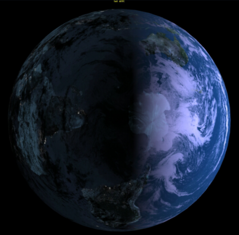
This tutorial shows how Adaptive Scalable Texture Compression (ASTC) can be easily used in simple scene, which is a textured sphere spinning in 3D space. It simulates an earth globe lighted from one side with a camera zooming in and out on its surface.

Warning
In order to use ASTC formats you need to run your application on hardware which supports corresponding OpenGL ES extension(s):
  • GL_KHR_texture_compression_astc_ldr or
  • GL_KHR_texture_compression_astc_hdr.
Otherwise, you will be getting messages about invalid format/internalformat passing through glCompressedTex* function to underlying graphics driver.

What is ASTC?

The ASTC algorithm represents a group of lossy block-based compressed texture image formats. For information on why texture compression is needed see chapter Why use texture compression? Two and three dimensional textures may be encoded using low or heigh dynamic range. In this demonstrating example we take under consideration only 2D, LDR textures. Basic concept of encoding relies on division the compressed image into a number of blocks with a uniform size. Each block is stored with a fixed 16-bytes footprint, regardless of the block's dimensions. That's why it can represent a varying number of texels and bit rate is determined by block size (see below table), which allows content developers to fine-tune the tradeoff of space against quality.

Block size Bit rate
4x4 8.00 bpp
5x4 6.40 bpp
5x5 5.12 bpp
6x5 4.27 bpp
6x6 3.56 bpp
8x5 3.20 bpp
8x6 2.67 bpp
8x8 2.00 bpp
10x5 2.56 bpp
10x6 2.13 bpp
10x8 1.60 bpp
10x10 1.28 bpp
12x10 1.07 bpp
12x12 0.89 bpp

ASTC offers also support for 1 to 4 color channels, together with modes for uncorrelated channels for use in mask textures and normal maps. Decoding one texel requires data from a single block only, which highly simplifies cache design, reduces bandwidth and improves encoder throughput. Despite this, ASTC achieves peak signal-to-noise ratios (PSNR) better than or comparable to existing texture compression algorithms (e.g. ETC1/ETC2).

Note
For more details on ASTC algorithm visit [1]

Texture preview

You can preview and analyse your texture image how it looks like after decompression using Texture Compression Tool (TCT):

  1. Download and install TCT from [2]
  2. Open your existing image file.
  3. Specify compression options in the ASTC tab which appears after pressing F7.
    TCTastcTab.png
  4. Confirm compression set up with OK. Preview is generated automatically.

Texture encoding

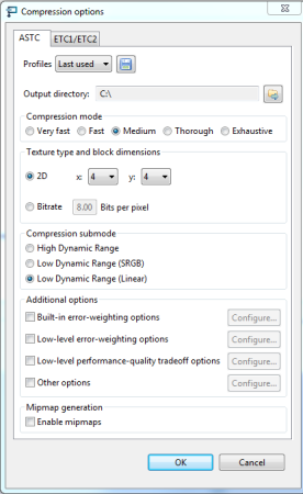
You can compress your texture image to ASTC format using command line interface:

  1. Download and install ASTC evaluation codec from [3]
  2. Compress you input image file to ASTC format using following syntax:
    astcenc.exe -c <inputfile> <outputfile> <rate> [options]
Note
For more information on how to use ASTC encoder just type:
astcenc.exe

Texture loading

In this sample sphere is covered with color that is result of combining colors from three texture units: cloud and gloss unit, day time unit and night time unit. Hence, firstly all compressed ASTC textures have to be decoded and specified for targets in order to generate texture bindings that will be next bound to particular texture units. For doing it load_texture() function is responsible, which follows the steps:

  • Texture image file is opened and loaded into local memory buffer.
  • Local buffer is mapped on ASTC header in order to extract texture image properties like ASTC block dimensions and sizes.
    /* ASTC header declaration. */
    typedef struct
    {
    unsigned char magic[4];
    unsigned char blockdim_x;
    unsigned char blockdim_y;
    unsigned char blockdim_z;
    unsigned char xsize[3];
    unsigned char ysize[3];
    unsigned char zsize[3];
  • Based on extracted texture properties the values of arguments passed to glCompressedTexImage2D are computed. Total number of bytes to be used by this call is computed by multiplying number of bytes per block and number of blocks which stands for:
    /* Merge x,y,z-sizes from 3 chars into one integer value. */
    xsize = astc_data_ptr->xsize[0] + (astc_data_ptr->xsize[1] << 8) + (astc_data_ptr->xsize[2] << 16);
    ysize = astc_data_ptr->ysize[0] + (astc_data_ptr->ysize[1] << 8) + (astc_data_ptr->ysize[2] << 16);
    zsize = astc_data_ptr->zsize[0] + (astc_data_ptr->zsize[1] << 8) + (astc_data_ptr->zsize[2] << 16);
    /* Compute number of blocks in each direction. */
    xblocks = (xsize + astc_data_ptr->blockdim_x - 1) / astc_data_ptr->blockdim_x;
    yblocks = (ysize + astc_data_ptr->blockdim_y - 1) / astc_data_ptr->blockdim_y;
    zblocks = (zsize + astc_data_ptr->blockdim_z - 1) / astc_data_ptr->blockdim_z;
    /* Each block is encoded on 16 bytes, so calculate total compressed image data size. */
    n_bytes_to_read = xblocks * yblocks * zblocks << 4;
  • Finally, glCompressedTexImage2D is invoked.

    GL_CHECK(glGenTextures(1, &to_id));
    GL_CHECK(glBindTexture(GL_TEXTURE_2D, to_id));
    /* Upload texture data to ES. */
    GL_CHECK(glCompressedTexImage2D(GL_TEXTURE_2D,
    0,
    compressed_data_internal_format,
    xsize,
    ysize,
    0,
    n_bytes_to_read,
    (const GLvoid*) astc_data_ptr));

    After a new texture ID has been generated texture object can be bound to target. Then, compressed data may be passed to driver.

  • Texture parameters are set up for GL_TEXTURE_2D target.

    GL_CHECK(glTexParameteri(GL_TEXTURE_2D, GL_TEXTURE_MAG_FILTER, GL_LINEAR));
    GL_CHECK(glTexParameteri(GL_TEXTURE_2D, GL_TEXTURE_MIN_FILTER, GL_LINEAR));
    GL_CHECK(glTexParameteri(GL_TEXTURE_2D, GL_TEXTURE_WRAP_S, GL_REPEAT));
    GL_CHECK(glTexParameteri(GL_TEXTURE_2D, GL_TEXTURE_WRAP_T, GL_REPEAT));

    Texture magnification and minification function are set to GL_LINEAR, which correspond to linear filtering. Texture filtering is a process of calculating color fragments from streched or shrunken texture map. Linear filtering works by applying the weighted average of the texels surrounding the texture coordinates. Texture wrapping modes are set to GL_REPEAT, which means that the textures will be repeated across the object.

Texture updating

Once we have got all texture bindings for GL_TEXTURE_2D target we are able to use and switch them at our convenience. It's a job of update_texture_bindings() function.

/* Update texture units with new bindings. */
GL_CHECK(glActiveTexture(GL_TEXTURE0));
GL_CHECK(glBindTexture(GL_TEXTURE_2D, texture_ids[current_texture_set_id].cloud_and_gloss_texture_id));
GL_CHECK(glActiveTexture(GL_TEXTURE1));
GL_CHECK(glBindTexture(GL_TEXTURE_2D, texture_ids[current_texture_set_id].earth_color_texture_id));
GL_CHECK(glActiveTexture(GL_TEXTURE2));
GL_CHECK(glBindTexture(GL_TEXTURE_2D, texture_ids[current_texture_set_id].earth_night_texture_id));

In each 5 sec texture bindings for texture units are refreshed following block size order from the table in section What is ASTC?

Visual output

You should see visual output similar to:

AstcTextures.png

Appendix: Mesh data flow

Generating vertex positions, texture coordinates and normal vectors is implemented based on spherical coordinate system. All mesh data are produced by solid sphere constructor.

class SolidSphere
{
public:
SolidSphere(const float radius, const unsigned int rings, const unsigned int sectors);
/* Mesh data accessors. */
float* getSphereVertexData(int* vertex_data_size);
float* getSphereNormalData(int* normal_data_size);
float* getSphereTexcoords (int* texcoords_size);
unsigned short* getSphereIndices(int* n_indices);
private:
float* sphere_vertices;
float* sphere_normals;
float* sphere_texcoords;
unsigned short* sphere_indices;
int sphere_vertex_data_size;
int sphere_normal_data_size;
int sphere_texcoords_size;
int sphere_n_indices;
};

User is responsible for passing radius, number of rings (parallels) and sectors (meridians) to the constructor. It computes coordinates for each vertex according to formulas:

sphericalCoordinates.png

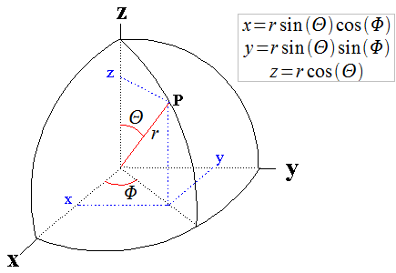
In such defined model space Φ changes from 0 to 360 degrees and Θ from 0 to 180 degrees. As it is depicted on figure, Θ range has to be divided by the number of rings and the range of Φ by the number of sectors. Smooth appearance of the sphere surface depends on a number of vertices.

const float R = 1.0f / (float)(rings - 1);
const float S = 1.0f / (float)(sectors - 1);
for (r = 0; r < rings; r++)
{
for (s = 0; s < sectors; s++)
{
const float x = sinf(M_PI * r * R) * cosf(2 * M_PI * s * S);
const float y = sinf(-M_PI_2 + M_PI * r * R);
const float z = sinf(2.0f * M_PI * s * S) * sinf(M_PI * r * R);
texcoords++ = s * S;
texcoords++ = r * R;
vertices++ = x * radius;
vertices++ = y * radius;
vertices++ = z * radius;
normals++ = x;
normals++ = y;
normals++ = z;
}
}

For a given vector position P on the sphere who's center is C, the normal is equal to norm(P - C), where norm normalizes the vector. Our sphere center is located at point C(0,0,0), which stands for normal(P - C) = norm(P) = vertices(x,y,z) / radius = (x,y,z). The reason why we generate normal vectors needed for light calculation is introduced in details here Normals

Texture coordinates indicating how to map an image onto mesh primitives are precisely covered in section Load Texture Function

Solid sphere constructor is also responsible for generating indices required for glDrawElements function. It has been assumed that each four vertices form two triangle primitives (GL_TRIANGLES mode), so glDrawElements call needs six vertex indices to construct them:

for (r = 0; r < rings; r++)
{
for (s = 0; s < sectors; s++)
{
/* First triangle. */
indices++ = r * sectors + s;
indices++ = r * sectors + (s + 1);
indices++ = (r + 1) * sectors + s;
/* Second triangle. */
indices++ = r * sectors + (s + 1);
indices++ = (r + 1) * sectors + (s + 1);
indices++ = (r + 1) * sectors + s;
}
}

In the next step generated vertex positions, normals and texture coordinates are loaded into buffer object.

/* Load generated mesh data from SolidSphere object. */
float* sphere_vertices = solid_sphere->getSphereVertexData(&sphere_vertices_size);
float* sphere_normals = solid_sphere->getSphereNormalData(&sphere_normals_size);
float* sphere_texcoords = solid_sphere->getSphereTexcoords(&sphere_texcoords_size);
/* Size of the entire buffer. */
GLsizei buffer_total_size = sphere_vertices_size + sphere_normals_size + sphere_texcoords_size;
/* Create buffer object to hold all mesh data. */
GL_CHECK(glGenBuffers(1, &bo_id));
GL_CHECK(glBindBuffer(GL_ARRAY_BUFFER, bo_id));
GL_CHECK(glBufferData(GL_ARRAY_BUFFER, buffer_total_size, NULL, GL_STATIC_DRAW));

After the above listing has executed, bo_id contains the unique ID of a buffer object that has been initialized to represent buffer_total_size bytes of storage. Passing GL_ARRAY_BUFFER as a binding point to refer to the buffer object suggests to OpenGL ES that we are about to put data in order to feed vertex attributes. Expected usage pattern of the data store is set to GL_STATIC_DRAW which signalizes graphics driver that buffer content will be set once, but used frequently for drawing.

Then, place the mesh data into the buffer object at the corresponding offsets:

/* Upload subsets of mesh data to buffer object. */
GL_CHECK(glBufferSubData(GL_ARRAY_BUFFER, 0, sphere_vertices_size, sphere_vertices));
buffer_offset += sphere_vertices_size;
GL_CHECK(glBufferSubData(GL_ARRAY_BUFFER, buffer_offset, sphere_normals_size, sphere_normals));
buffer_offset += sphere_normals_size;
GL_CHECK(glBufferSubData(GL_ARRAY_BUFFER, buffer_offset, sphere_texcoords_size, sphere_texcoords));
Note
In this step the data are copied from a local memory storage to update buffer object's content. Immediately after this, memory pointed by the sphere_vertices, sphere_normals and sphere_texcoords pointers may be freed.

Before we can go on, let's create a vertex array object to store vertex array state.

GL_CHECK(glGenVertexArrays(1, &vao_id));
GL_CHECK(glBindVertexArray(vao_id));

Once it is generated and bound, we are able to fill in its content. The goal is to determine OpenGL ES to connect vertex attributes values directly with the data stored in the supplied buffer object.

GL_CHECK(glEnableVertexAttribArray(position_location));
GL_CHECK(glEnableVertexAttribArray(normal_location));
GL_CHECK(glEnableVertexAttribArray(texture_coords_location));
/* Populate attribute for position. */
GL_CHECK(glVertexAttribPointer(position_location, 3, GL_FLOAT, GL_FALSE, 0, (const GLvoid*) buffer_offset));
buffer_offset += sphere_vertices_size;
/* Populate attribute for normals. */
GL_CHECK(glVertexAttribPointer(normal_location, 3, GL_FLOAT, GL_FALSE, 0, (const GLvoid*) buffer_offset));
buffer_offset += sphere_normals_size;
/* Populate attribute for texture coordinates. */
GL_CHECK(glVertexAttribPointer(texture_coords_location, 2, GL_FLOAT, GL_FALSE, 0, (const GLvoid*) buffer_offset));

Automatic filling of the attributes is enabled with glEnableVertexAttribArray calls. Next, we have to inform graphics driver where the data is and turn on vertex fetching for all attributes. Whereas a non-zero buffer is currently bound to the GL_ARRAY_BUFFER target, last argument in glVertexAttribPointer function specifies an offset in the data store of that buffer.

Sphere lighting

This sample uses Phong lighting model which has been explained in details in section Lighting

References

[1] http://www.khronos.org/registry/gles/extensions/KHR/texture_compression_astc_hdr.txt

[2] http://malideveloper.arm.com/develop-for-mali/tools/asset-creation/mali-gpu-texture-compression-tool/

[3] http://malideveloper.arm.com/develop-for-mali/tools/astc-evaluation-codec/