OpenGL ES SDK for Android ARM Developer Center
 All Classes Namespaces Files Functions Variables Typedefs Enumerations Enumerator Friends Macros Pages
Projected Lights

Projected Lights effect using OpenGL ES 3.0.

Introduction

This tutorial assumes that you already have basic OpenGL ES knowledge, and have read and understood the Normal Mapping, Lighting and Texture Cube tutorials.

Overview

ProjectedLights.png
Projected Lights effect: the direction of the projected lights changes during rendering.

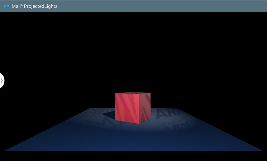
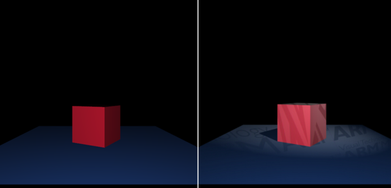
The application shows the projected lights effect. There is a spot light effect adjusted to display the texture instead of the normal light colour. There is also a shadow map technique used to make the scene more realistic by applying some shadows.

The projected lights effect is implemented in two basic steps, described below:

  • Calculating the shadow map.
    • The scene is rendered from spot light's point of view.
    • The result is stored in the depth texture, which is called a shadow map.
    • The shadow map will be used in next steps to verify whether a fragment should be lit by the spot light or should be obscured by shadow.
  • Scene rendering.
    • The scene (which consists of a plane, on top of which is placed a single cube) is rendered from camera's point of view.
    • Directional lighting is implemented to accentuate the 3D scene with the perspective.
    • A spot light effect is implemented, however it is adjusted to display texture rather than a simple colour.
    • Shadows are computed for the spot lighting (the result of the first step is now used).

Render geometry

In the application we are rendering a horizontally located plane, on top of which we lay a single cube. Let us now focus on the geneating the geometry that will be rendered.

ProjectedLightsGeometry.png
Vertex coordinates of the geometry that will be rendered.

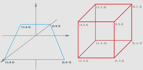
First of all, we need to have the coordinates of vertices that make up a cubic or plane shape. Please note that there will also be lighting applied, which means that we will need normals as well.

Geometry data will be stored and then used by objects that are generated with the following commands:

/* Generate buffer objects. */
GL_CHECK(glGenBuffers(1, &renderSceneObjects.renderCube.coordinatesBufferObjectId));
GL_CHECK(glGenBuffers(1, &renderSceneObjects.renderCube.normalsBufferObjectId));
GL_CHECK(glGenBuffers(1, &renderSceneObjects.renderPlane.coordinatesBufferObjectId));
GL_CHECK(glGenBuffers(1, &renderSceneObjects.renderPlane.normalsBufferObjectId));
/* Generate vertex array objects. */
GL_CHECK(glGenVertexArrays(1, &renderSceneObjects.renderCube.vertexArrayObjectId));
GL_CHECK(glGenVertexArrays(1, &renderSceneObjects.renderPlane.vertexArrayObjectId));

Geometry data is then generated and copied to specific buffer objects. For more details of how the coordinates of vertices are calculated, please refer to the implementation of those functions.

/* Please see the specification above. */
static void setupGeometryData()
{
/* Get triangular representation of the scene cube. Store the data in the cubeCoordinates array. */
CubeModel::getTriangleRepresentation(&cubeGeometryProperties.coordinates,
/* Calculate normal vectors for the scene cube created above. */
CubeModel::getNormals(&cubeGeometryProperties.normals,
/* Get triangular representation of a square to draw plane in XZ space. Store the data in the planeCoordinates array. */
PlaneModel::getTriangleRepresentation(&planeGeometryProperties.coordinates,
/* Calculate normal vectors for the plane. Store the data in the planeNormals array. */
PlaneModel::getNormals(&planeGeometryProperties.normals,
/* Fill buffer objects with data. */
/* Buffer holding coordinates of triangles which make up the scene cubes. */
GL_CHECK(glBindBuffer(GL_ARRAY_BUFFER,
renderSceneObjects.renderCube.coordinatesBufferObjectId));
GL_CHECK(glBufferData(GL_ARRAY_BUFFER,
GL_STATIC_DRAW));
/* Buffer holding coordinates of normal vectors for each vertex of the scene cubes. */
GL_CHECK(glBindBuffer(GL_ARRAY_BUFFER,
renderSceneObjects.renderCube.normalsBufferObjectId));
GL_CHECK(glBufferData(GL_ARRAY_BUFFER,
GL_STATIC_DRAW));
/* Buffer holding coordinates of triangles which make up the plane. */
GL_CHECK(glBindBuffer(GL_ARRAY_BUFFER,
renderSceneObjects.renderPlane.coordinatesBufferObjectId));
GL_CHECK(glBufferData(GL_ARRAY_BUFFER,
GL_STATIC_DRAW));
/* Buffer holding coordinates of the plane's normal vectors. */
GL_CHECK(glBindBuffer(GL_ARRAY_BUFFER,
renderSceneObjects.renderPlane.normalsBufferObjectId));
GL_CHECK(glBufferData(GL_ARRAY_BUFFER,
GL_STATIC_DRAW));
}

In the program object, geometry vertices are referred to via the attributes, which is rather obvious.

/* ATTRIBUTES */
in vec4 vertexCoordinates; /* Attribute: holding coordinates of triangles that make up a geometry. */
in vec3 vertexNormals; /* Attribute: holding normals. */

This is why we need to query for the attribute location within the program object responsible for scene rendering (note that all of the following functions need to be called for the active program object).

locationsStoragePtr->attributeVertexCoordinates = GL_CHECK(glGetAttribLocation (programObjectId, "vertexCoordinates"));
locationsStoragePtr->attributeVertexNormals = GL_CHECK(glGetAttribLocation (programObjectId, "vertexNormals"));

As you can see above, we are querying for the coordinates only, without specifying the cube or plane ones. This is because we are using only one program object to render both the plane and cube. Rendering specific geometry is achieved by using proper Vertex Attrib Arrays. Let's look at how it is implemented.

/* Enable cube VAAs. */
GL_CHECK(glBindVertexArray (renderSceneObjects.renderCube.vertexArrayObjectId));
GL_CHECK(glBindBuffer (GL_ARRAY_BUFFER,
renderSceneObjects.renderCube.coordinatesBufferObjectId));
GL_CHECK(glVertexAttribPointer (renderSceneProgramLocations.attributeVertexCoordinates,
NUMBER_OF_POINT_COORDINATES,
GL_FLOAT,
GL_FALSE,
0,
NULL));
GL_CHECK(glBindBuffer (GL_ARRAY_BUFFER,
renderSceneObjects.renderCube.normalsBufferObjectId));
GL_CHECK(glVertexAttribPointer (renderSceneProgramLocations.attributeVertexNormals,
NUMBER_OF_POINT_COORDINATES,
GL_FLOAT,
GL_FALSE,
0,
NULL));
GL_CHECK(glEnableVertexAttribArray(renderSceneProgramLocations.attributeVertexCoordinates));
GL_CHECK(glEnableVertexAttribArray(renderSceneProgramLocations.attributeVertexNormals));
/* Enable plane VAAs. */
GL_CHECK(glBindVertexArray (renderSceneObjects.renderPlane.vertexArrayObjectId));
GL_CHECK(glBindBuffer (GL_ARRAY_BUFFER,
renderSceneObjects.renderPlane.coordinatesBufferObjectId));
GL_CHECK(glVertexAttribPointer (renderSceneProgramLocations.attributeVertexCoordinates,
NUMBER_OF_POINT_COORDINATES,
GL_FLOAT,
GL_FALSE,
0,
NULL));
GL_CHECK(glBindBuffer (GL_ARRAY_BUFFER,
renderSceneObjects.renderPlane.normalsBufferObjectId));
GL_CHECK(glVertexAttribPointer (renderSceneProgramLocations.attributeVertexNormals,
NUMBER_OF_POINT_COORDINATES,
GL_FLOAT,
GL_FALSE,
0,
NULL));
GL_CHECK(glEnableVertexAttribArray(renderSceneProgramLocations.attributeVertexCoordinates));
GL_CHECK(glEnableVertexAttribArray(renderSceneProgramLocations.attributeVertexNormals));

And now, by calling glBindVertexArray() with the proper parameter, we can control which object: cube or plane is going to be rendered. Please refer to:

/* Set cube's coordinates to be used within a program object. */
GL_CHECK(glBindVertexArray(renderSceneObjects.renderCube.vertexArrayObjectId));
/* Set plane's coordinates to be used within a program object. */
GL_CHECK(glBindVertexArray(renderSceneObjects.renderPlane.vertexArrayObjectId));

The final thing is to make the actual draw call, which can be achieved by:

GL_CHECK(glDrawArrays(GL_TRIANGLES,
0,
GL_CHECK(glDrawArrays(GL_TRIANGLES,
0,

Calculate a shadow map

To calculate the shadow map we need to create a depth texture, which will be used to store the results. It is achieved in some basic steps, which you should already know, but let us describe this one more time.

Generate texture object and bind it to the GL_TEXTURE_2D target.

GL_CHECK(glGenTextures (1,
&renderSceneObjects.depthTextureObjectId));
GL_CHECK(glBindTexture (GL_TEXTURE_2D,
renderSceneObjects.depthTextureObjectId));

Specify the texture storage data type.

GL_CHECK(glTexStorage2D(GL_TEXTURE_2D,
1,
GL_DEPTH_COMPONENT24,

We wanted our shadow to be more precise, this is why the depth texture resolution is bigger than normal scene size. Please refer to:

/* Store window size. */
/* Calculate size of a shadow map texture that will be used. */

Set texture object parameters. The new thing here is to set GL_TEXTURE_COMPARE_MODE to the value of GL_COMPARE_REF_TO_TEXTURE which leads to r texture coordinate to be compared to the value in the currently bound depth texture.

GL_CHECK(glTexParameteri(GL_TEXTURE_2D,
GL_TEXTURE_MIN_FILTER,
GL_LINEAR));
GL_CHECK(glTexParameteri(GL_TEXTURE_2D,
GL_TEXTURE_MAG_FILTER,
GL_LINEAR));
GL_CHECK(glTexParameteri(GL_TEXTURE_2D,
GL_TEXTURE_WRAP_S,
GL_CLAMP_TO_EDGE));
GL_CHECK(glTexParameteri(GL_TEXTURE_2D,
GL_TEXTURE_WRAP_T,
GL_CLAMP_TO_EDGE));
GL_CHECK(glTexParameteri(GL_TEXTURE_2D,
GL_TEXTURE_WRAP_R,
GL_CLAMP_TO_EDGE));
GL_CHECK(glTexParameteri(GL_TEXTURE_2D,
GL_TEXTURE_COMPARE_FUNC,
GL_LEQUAL));
GL_CHECK(glTexParameteri(GL_TEXTURE_2D,
GL_TEXTURE_COMPARE_MODE,
GL_COMPARE_REF_TO_TEXTURE));

The next thing we have to do to implement the render to texture mechanism is to:

  • Generate framebuffer object.
GL_CHECK(glGenFramebuffers (1,
&renderSceneObjects.framebufferObjectId));
GL_CHECK(glBindFramebuffer (GL_FRAMEBUFFER,
renderSceneObjects.framebufferObjectId));
  • Bind the depth texture object to the depth attachment of the framebuffer object.
GL_CHECK(glFramebufferTexture2D(GL_FRAMEBUFFER,
GL_DEPTH_ATTACHMENT,
GL_TEXTURE_2D,
renderSceneObjects.depthTextureObjectId,
0));

We have to use proper view-projection matrices while rendering. It is important to mention here that our spot light position is constant during the rendering process, but its direction is changing, which means the point at which the spot light is directed is updated per frame.

/* Please see the specification above. */
{
/* Time used to set light direction and position. */
const float currentAngle = timer.getTime() / 4.0f;
/* Update the look at point coordinates. */
lightViewProperties.lookAtPoint.x = SPOT_LIGHT_TRANSLATION_RADIUS * sinf(currentAngle);
lightViewProperties.lookAtPoint.y = -1.0f;
lightViewProperties.lookAtPoint.z = SPOT_LIGHT_TRANSLATION_RADIUS * cosf(currentAngle);
/* Update all the view, projection matrixes athat are connected with updated look at point coordinates. */
Vec4f lookAtPoint = {lightViewProperties.lookAtPoint.x,
lightViewProperties.lookAtPoint.y,
lightViewProperties.lookAtPoint.z,
1.0f};
/* Get lookAt matrix from the light's point of view, directed at the center of a plane.
* Store result in viewMatrixForShadowMapPass. */
lightViewProperties.viewMatrix = Matrix::matrixLookAt(lightViewProperties.position,
lightViewProperties.lookAtPoint,
lightViewProperties.cubeViewProperties.modelViewMatrix = lightViewProperties.viewMatrix * lightViewProperties.cubeViewProperties.modelMatrix;
lightViewProperties.planeViewProperties.modelViewMatrix = lightViewProperties.viewMatrix * lightViewProperties.planeViewProperties.modelMatrix;
lightViewProperties.cubeViewProperties.modelViewProjectionMatrix = lightViewProperties.projectionMatrix * lightViewProperties.cubeViewProperties.modelViewMatrix;
lightViewProperties.planeViewProperties.modelViewProjectionMatrix = lightViewProperties.projectionMatrix * lightViewProperties.planeViewProperties.modelViewMatrix;
cameraViewProperties.spotLightLookAtPointInEyeSpace = Matrix::vertexTransform(&lookAtPoint, &cameraViewProperties.viewMatrix);
Matrix inverseCameraViewMatrix = Matrix::matrixInvert(&cameraViewProperties.viewMatrix);
/* [Define colour texture translation matrix] */
Matrix colorTextureTranslationMatrix = Matrix::createTranslation(COLOR_TEXTURE_TRANSLATION,
0.0f,
/* [Define colour texture translation matrix] */
/* [Calculate matrix for shadow map sampling: colour texture] */
cameraViewProperties.viewToColorTextureMatrix = Matrix::biasMatrix *
lightViewProperties.projectionMatrix *
lightViewProperties.viewMatrix *
colorTextureTranslationMatrix *
inverseCameraViewMatrix;
/* [Calculate matrix for shadow map sampling: colour texture] */
/* [Calculate matrix for shadow map sampling: depth texture] */
cameraViewProperties.viewToDepthTextureMatrix = Matrix::biasMatrix *
lightViewProperties.projectionMatrix *
lightViewProperties.viewMatrix *
inverseCameraViewMatrix;
/* [Calculate matrix for shadow map sampling: depth texture] */
}

There are different matrices used for rendering cube and plane form spot light point of view. Call glUniformMatrix4fv() to update the uniform values.

/* Use matrices specific for rendering a scene from spot light perspective. */
GL_CHECK(glUniformMatrix4fv(renderSceneProgramLocations.uniformModelViewMatrix,
1,
GL_FALSE,
lightViewProperties.cubeViewProperties.modelViewMatrix.getAsArray()));
GL_CHECK(glUniformMatrix4fv(renderSceneProgramLocations.uniformModelViewProjectionMatrix,
1,
GL_FALSE,
lightViewProperties.cubeViewProperties.modelViewProjectionMatrix.getAsArray()));
GL_CHECK(glUniformMatrix4fv(renderSceneProgramLocations.uniformNormalMatrix,
1,
GL_FALSE,
lightViewProperties.cubeViewProperties.normalMatrix.getAsArray()));
/* Use matrices specific for rendering a scene from spot light perspective. */
GL_CHECK(glUniformMatrix4fv(renderSceneProgramLocations.uniformModelViewMatrix,
1,
GL_FALSE,
lightViewProperties.planeViewProperties.modelViewMatrix.getAsArray()));
GL_CHECK(glUniformMatrix4fv(renderSceneProgramLocations.uniformModelViewProjectionMatrix,
1,
GL_FALSE,
lightViewProperties.planeViewProperties.modelViewProjectionMatrix.getAsArray()));
GL_CHECK(glUniformMatrix4fv(renderSceneProgramLocations.uniformNormalMatrix,
1,
GL_FALSE,
lightViewProperties.planeViewProperties.normalMatrix.getAsArray()));

Owing to the fact that the shadow map texture is bigger than the normal scene (as already mentioned above), we have to remember to adjust the viewport.

/* Set the view port to size of shadow map texture. */

Our scene is rather simple: there is only one cube placed on the top of a plane. We can introduce some optimisation here, which means the back faces will be culled. We are also setting the polygon offset to eliminate z-fighting in the shadows. Those settings are used only if enabled.

/* Set the Polygon offset, used when rendering the into the shadow map
* to eliminate z-fighting in the shadows (if enabled). */
GL_CHECK(glPolygonOffset(1.0f, 0.0f));
/* Set back faces to be culled (only when GL_CULL_FACE mode is enabled). */
GL_CHECK(glCullFace(GL_BACK));
GL_CHECK(glEnable(GL_POLYGON_OFFSET_FILL));

What we need to do is to enable depth testing. When this is enabled, the depth values will be compared and the result will be stored in the depth buffer.

/* Enable depth test to do comparison of depth values. */
GL_CHECK(glEnable(GL_DEPTH_TEST));

In this step, we want to generate the depth values only, which means we are allowed to disable writing to each framebuffer colour component.

/* Disable writing of each frame buffer colour component. */
GL_CHECK(glColorMask(GL_FALSE, GL_FALSE, GL_FALSE, GL_FALSE));

Finally we are ready for the actual rendering.

If we would like to use the generated depth texture data in a program object, it is enough to query for a shadow sampler uniform location and set the depth texture object as input value for this uniform.

locationsStoragePtr->uniformShadowMap = GL_CHECK(glGetUniformLocation (programObjectId, "shadowMap"));
GL_CHECK(glActiveTexture(GL_TEXTURE0 + TEXTURE_UNIT_FOR_SHADOW_MAP_TEXTURE));
GL_CHECK(glBindTexture (GL_TEXTURE_2D,
renderSceneObjects.depthTextureObjectId));

More details about the program object and the scene rendering will be described in the following sections: Generate and use colour texture and Projecting a texture.

Generate and use colour texture

There is a colour texture projected onto the scene, which is why we need to generate a texture object filled with data. This is achieved in some basic steps as described below.

ProjectedLightsTexture.bmp
Image that will be projected onto a screen.

Set active texture unit for colour texture.

GL_CHECK(glActiveTexture(GL_TEXTURE0 + TEXTURE_UNIT_FOR_COLOR_TEXTURE));

Generate and bind texture object.

GL_CHECK(glGenTextures (1,
&renderSceneObjects.colorTextureObjectId));
GL_CHECK(glBindTexture (GL_TEXTURE_2D,
renderSceneObjects.colorTextureObjectId));

Load BMP image data.

Texture::loadBmpImageData(COLOR_TEXTURE_NAME, &imageWidth, &imageHeight, &textureData);

Set texture object data.

GL_CHECK(glTexStorage2D (GL_TEXTURE_2D,
1,
GL_RGB8,
imageWidth,
imageHeight));
GL_CHECK(glTexSubImage2D(GL_TEXTURE_2D,
0,
0,
0,
imageWidth,
imageHeight,
GL_RGB,
GL_UNSIGNED_BYTE,
textureData));

Set texture object parameters.

GL_CHECK(glTexParameteri(GL_TEXTURE_2D,
GL_TEXTURE_MIN_FILTER,
GL_LINEAR));
GL_CHECK(glTexParameteri(GL_TEXTURE_2D,
GL_TEXTURE_MAG_FILTER,
GL_LINEAR));
GL_CHECK(glTexParameteri(GL_TEXTURE_2D,
GL_TEXTURE_WRAP_R,
GL_REPEAT));
GL_CHECK(glTexParameteri(GL_TEXTURE_2D,
GL_TEXTURE_WRAP_S,
GL_REPEAT));
GL_CHECK(glTexParameteri(GL_TEXTURE_2D,
GL_TEXTURE_WRAP_T,
GL_REPEAT));

Now, if we would like to use the texture within the program object, we need to query for the colour texture object uniform sampler location (note that following commands are called for active program object).

locationsStoragePtr->uniformColorTexture = GL_CHECK(glGetUniformLocation (programObjectId, "colorTexture"));

Then we are ready to associate uniform sampler with texture object by calling

Projecting a texture

Finally, we are ready to describe the mechanism of projecting a texture.

If you follow the instructions described in the previous sections (Render geometry, Calculate a shadow map, Generate and use colour texture) you will be ready to focus on the projected lights mechanism.

We are using only one program object in this tutorial. The vertex shader is rather simple (presented below). It is used for translating coordinates into eye- and NDC-space (which is the eye-space with the perspective applied).

/* [Define attributes] */
/* ATTRIBUTES */
in vec4 vertexCoordinates; /* Attribute: holding coordinates of triangles that make up a geometry. */
in vec3 vertexNormals; /* Attribute: holding normals. */
/* [Define attributes] */
/* UNIFORMS */
uniform mat4 modelViewMatrix; /* Model * View matrix */
uniform mat4 modelViewProjectionMatrix; /* Model * View * Projection matrix */
uniform mat4 normalMatrix; /* transpose(inverse(Model * View)) matrix */
/* OUTPUTS */
out vec3 normalInEyeSpace; /* Normal vector for the coordinates. */
out vec4 vertexInEyeSpace; /* Vertex coordinates expressed in eye space. */
void main()
{
/* Calculate and set output vectors. */
normalInEyeSpace = mat3x3(normalMatrix) * vertexNormals;
vertexInEyeSpace = modelViewMatrix * vertexCoordinates;
/* Multiply model-space coordinates by model-view-projection matrix to bring them into eye-space. */
gl_Position = modelViewProjectionMatrix * vertexCoordinates;
}

Please note that depth values are calculated from spot light's point of view. If we would like to use them while rendering the scene from camera's point of view, we would have to apply a translation from one space to another. Please look at the schema below.

ProjectedLightsMatrixSchema.png
Camera and spot light spaces schema.

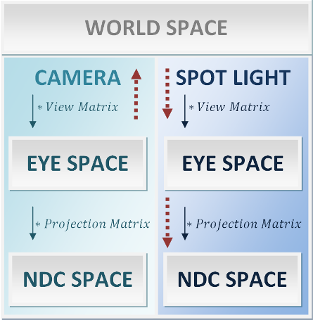
Our shadow map (the texture object containing depth values) is computed in spot light's NDC space, however we would need depth values in camera eye space. To achieve that, we would take a fragment from camera eye space and translate it to spot light NDC space in order to query for its depth value. We need to calculate a matrix which will help us with that. The idea is marked at the schema with red arrows.

cameraViewProperties.viewToDepthTextureMatrix = Matrix::biasMatrix *
lightViewProperties.projectionMatrix *
lightViewProperties.viewMatrix *
inverseCameraViewMatrix;

The bias matrix is used to map values from a range <-1, 1> (eye space coordinates) to <0, 1> (texture coordinates).

/* Bias matrix. */
const float Matrix::biasArray[16] =
{
0.5f, 0.0f, 0.0f, 0.0f,
0.0f, 0.5f, 0.0f, 0.0f,
0.0f, 0.0f, 0.5f, 0.0f,
0.5f, 0.5f, 0.5f, 1.0f,
};

Analogous mechanism need to be used for sampling the colour texture. The only difference is that we want to fit the colour texture in the view, so that the texture is smaller and repeated multiple times.

Matrix colorTextureTranslationMatrix = Matrix::createTranslation(COLOR_TEXTURE_TRANSLATION,
0.0f,
cameraViewProperties.viewToColorTextureMatrix = Matrix::biasMatrix *
lightViewProperties.projectionMatrix *
lightViewProperties.viewMatrix *
colorTextureTranslationMatrix *
inverseCameraViewMatrix;

In the fragment shader, we are dealing with two types of lighting:

  • Directional lighting, which is implemented as presented below. We will not focus on this type of lighting here, as it should be already well known to a reader. If not, please refer to previous tutorials.
vec4 calculateLightFactor()
{
vec3 normalizedNormal = normalize(normalInEyeSpace);
vec3 normalizedLightDirection = normalize(directionalLightPosition - vertexInEyeSpace.xyz);
vec4 result = vec4(directionalLightColor, 1.0) * max(dot(normalizedNormal, normalizedLightDirection), 0.0);
return result * directionalLightAmbient;
}
  • Spot lighting, which is the same as projected texturing and will be now explained in more details.

First of all, we need to verify whether the fragment is placed inside or outside the spot light cone. This is checked by calculating the angle between the vector from light source to the fragment and vector from light source to point into which light is directed. If the anngle is bigger than the spot light angle, it means the fragment is outside the spot light cone, if smaller - inside.

float getFragmentToLightCosValue()
{
vec4 fragmentToLightdirection = normalize(vertexInEyeSpace - spotLightPositionInEyeSpace);
vec4 spotLightDirection = normalize(spotLightLookAtPointInEyeSpace- spotLightPositionInEyeSpace);
float cosine = dot(spotLightDirection, fragmentToLightdirection);
return cosine;
}

The next step is to verify whether the fragment should be shadowed or lit by the spot light. This is done by sampling shadow map texture and comparing the result with the scene depth.

/* Depth value retrieved from the shadow map. */
float shadowMapDepth = textureProj(shadowMap, normalizedVertexPositionInTexture);
/* Depth value retrieved from drawn model. */
float modelDepth = normalizedVertexPositionInTexture.z;

If the fragment is inside the light cone and not in the shadow, the projected texture colour should be applied on it.

vec4 calculateProjectedTexture()
{
vec3 textureCoordinates = (viewToColorTextureMatrix * vertexInEyeSpace).xyz;
vec3 normalizedTextureCoordinates = normalize(textureCoordinates);
vec4 textureColor = textureProj(colorTexture, normalizedTextureCoordinates);
return textureColor;
}
vec4 calculateSpotLight(float fragmentToLightCosValue)
{
const float constantAttenuation = 0.01;
const float linearAttenuation = 0.001;
const float quadraticAttenuation = 0.0004;
vec4 result = vec4(0.0);
/* Calculate the distance from a spot light source to fragment. */
float distance = distance(vertexInEyeSpace.xyz, spotLightPositionInEyeSpace.xyz);
float factor = clamp((fragmentToLightCosValue - spotLightCosAngle), 0.0, 1.0);
float attenuation = 1.0 / (constantAttenuation +
linearAttenuation * distance +
quadraticAttenuation * distance * distance);
vec4 projectedTextureColor = calculateProjectedTexture();
result = (spotLightColor * 0.5 + projectedTextureColor)* factor * attenuation;
return result;
}
/* Apply spot lighting and shadowing if needed). */
if ((fragmentToLightCosValue > spotLightCosAngle) && /* If fragment is in spot light cone. */
modelDepth < shadowMapDepth + EPSILON)
{
vec4 spotLighting = calculateSpotLight(fragmentToLightCosValue);
color += spotLighting;
}

After those operations are applied, we get the result as shown on the images below.

ProjectedLightsResult.png
The result of the rendering: when only the directional lighting is applied (on the left) and when projected lights are applied (on the right).