 |
Network Component
MDK Middleware for IPv4 and IPv6 Networking
|

|
|
Network Component
MDK Middleware for IPv4 and IPv6 Networking
|
|
The steps to create a microcontroller application that uses TCP/IP communication are:
Only a few steps are necessary to complete the RTE Component selection:
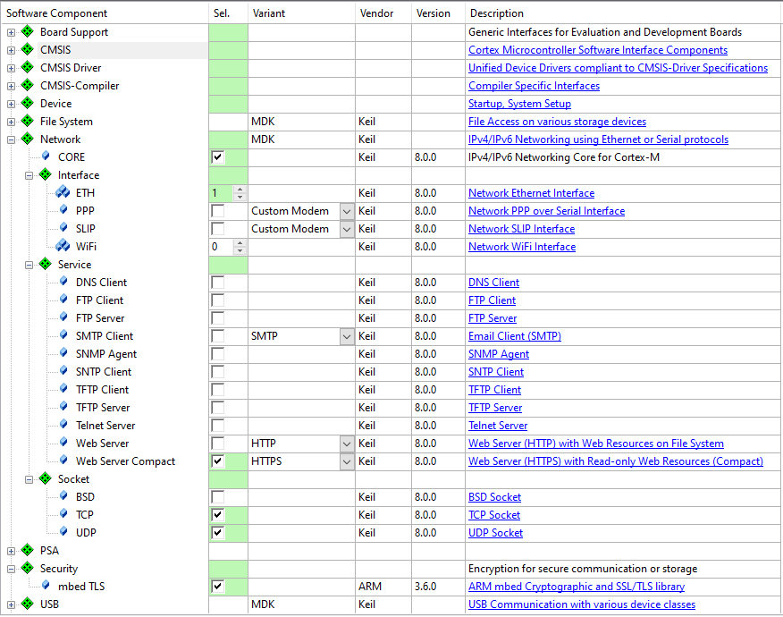
The Network Device Driver and the Network Controller of the microcontroller need to be correctly configured. This means:
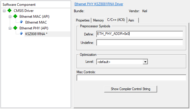
For Ethernet network communication, usually an external Ethernet PHY is required to interface the physical line to the digital MAC of the microcontroller device. The MAC usually contains two buses:
SMI is used to access the PHY’s internal registers to read the state of the link (up/down), duplex mode, speed, and to restart auto-negotiation etc. SMI is a serial bus, which allows to connect up to 32 devices. Devices on the bus are accessed using a 5-bit device address. A default device address is hardware configurable by pin-strapping on the device (some pins are sampled when a reset is asserted or at power-up).
The device’s internal weak pull-up or pull-down resistors define a default device address. This address can be changed by connecting strong pull-up or pull-down resistors externally. In this case, the ETH_PHY_ADDR in the PHY driver needs to be changed accordingly to be able to control the PHY and to communicate with it. In µVision use the Options for Component dialog to override the default setting for ETH_PHY_ADDR:
All configuration files for the Network Component are listed in the Project window below the Component Class Network.
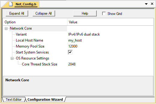
The configuration file Network Core Net_Config.h contains the setting for the library version to be used in the application.
The following Variant options are available:
The Local Host Name specifies a name under which the network device can be accessed on a local area network (LAN). This requires a NetBIOS Name Service to be enabled in the configuration. This name is very useful if you don't know the IP address that has been assigned to your device by the DHCP server.
The Memory Pool Size specifies the amount of RAM in bytes allocated for the memory pool. The buffers for the network packets are allocated from this memory pool. Usually, the default value of 12000 bytes is sufficient.
Many Network Services are started by the Network Core automatically. If you disable Start System Services, you need to enable/start them at runtime using the dedicated functions for that.
To change the default OS resource settings for the Network Core, use Core Thread Stack Size. The default value is 2048 bytes. The default Core Thread priority is osPriorityNormal. You can change this priority by changing the NET_THREAD_PRIORITY defined in this configuration file. This priority must be lower than the priorities of the network interface threads.
The Network Interface configuration files Net_Config_Interface_n.h contain general IP address and other settings. You also need to specify the hardware driver number that is to be used with the network interface. In case of Ethernet for example, this is usually 0. If you are using a SLIP or PPP over a serial connection, you need to specify the hardware driver number of the exact UART you wish to use. All settings for the different interfaces are described here:
Usually, the needs of most applications are served by using the default settings for the sockets. Of course, there are configuration files for all three socket types that are specified in
The configuration files for all the Network Services are explained in the respective section:
The mbed TLS component provides an API for secure communication. When selecting this software component, the mbedTLS_config.h configuration file is added to the project. The proper usage of this file is out of the scope of this document. For further information, check the online documentation of .
For proper operation, the Network Component requires some system configuration settings. The requirements are:
netCore_Thread and netETH_Thread).For more information, check the Network Component's Resource Requirements section.
Before using the networking communications, the Network Core must be initialized with the function netInitialize. The function initializes the Network system resources and creates threads and other RTOS objects. The initialization is usually executed from the app_main thread.
The initialization process is different depending on which network interface is used:
files provide access to all functions that are required to communicate over the Network. The available functions are explained in the Reference section of the Network Component. These routines can be adapted to the needs of the microcontroller application, in case more functionality is needed.
The following templates are available for the Network component:
| Template Name | User Functions |
|---|---|
| DNS_Client.c | dns_cbfunc (Callback function for notification about DNS client events), resolve_host (DNS resolving process) |
| FTP_Client_UIF.c | netFTPc_Process (Request parameters for FTP client session), netFTPc_Notify (Notify the user application when FTP client operation ends) |
| FTP_Server_Access.c | netFTPs_AcceptClient (Accept or deny connection from remote FTP client) |
| FTP_Server_Event.c | netFTPs_Notify (Notify the user application about events in FTP server service) |
| FTP_Server_Multiuser.c | netFTPs_CheckUsername (Check if an user account exists), netFTPs_CheckPassword (Check user account password), netFTPs_FileAccess (Check if remote user is allowed to access a file) |
| HTTP_Server_Access.c | netHTTPs_AcceptClient (Accept or deny connection from remote HTTP client) |
| HTTP_Server_CGI.c | netCGI_ProcessQuery (Process query string received by GET request), netCGI_ProcessData (Process data received by POST request), netCGI_Script (Generate dynamic web data from a script line) |
| HTTP_Server_Error.c | net_http_error (Define user-friendly HTTP error messages) |
| HTTP_Server_Multiuser.c | netHTTPs_CheckAccount (Check if an user account exists), netHTTPs_FileAccess (Check if remote user is allowed to access a file) |
| SMTP_Client_UIF.c | netSMTPc_Process (Request parameters for SMTP client session), netSMTPc_Notify (Notify the user application when SMTP client operation ends), netSMTPc_AcceptAuthentication (Accept or deny authentication requested by SMTP server) |
| SNMP_Agent_MIB.c | mib_table (Defines MIB information data table), register_mib_table (Registers a MIB table in SNMP agent) |
| TCP_Socket_Client.c | tcp_cb_client (Notify the user application about TCP socket events), send_data (Connect to TCP server and send data) |
| TCP_Socket_Server.c | tcp_cb_server (Notify the user application about TCP socket events) |
| Telnet_Server_Access.c | netTELNETs_AcceptClient (Accept or deny connection from remote Telnet client) |
| Telnet_Server_Multiuser.c | netTELNETs_CheckUsername (Check if an user account exists), netTELNETs_CheckPassword (Check user account password) |
| Telnet_Server_UIF.c | netTELNETs_ProcessMessage (Request message for Telnet server session), netTELNETs_ProcessCommand (Process a command and generate response) |
| TFTP_Client_UIF.c | tftp_client_notify (Notify the user application when TFTP client operation ends) |
| TFTP_Server_Access.c | netTFTPs_AcceptClient (Accept or deny connection from remote TFTP client) |
| UDP_Socket.c | udp_cb_func (Notify the user application about UDP socket events), send_udp_data (Send UDP data to destination client) |
Network Component can be easily configured to generate debug events and provide dynamic visibility to the component operation.
Network supports event annotations for the and makes it very easy to analyze the internal operation of the Network Component during application debugging. The old STDIO debug, which outputs event information as ASCII messages on the standard output device, is also supported.
The Network Component debug is configured using the Net_Debug.h file. The options are set in the file directly or using the Configuration Wizard.
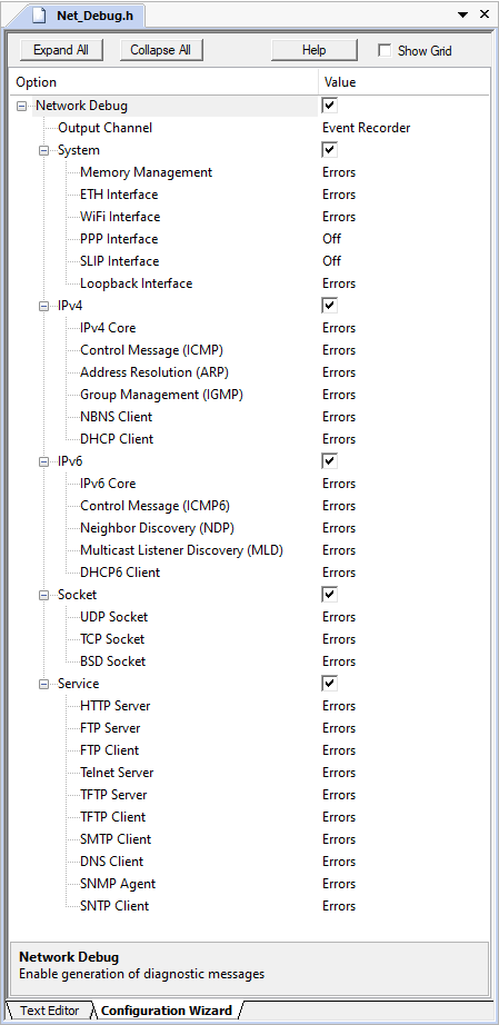
The following settings are available:
The debugging configuration settings are divided into groups that can be activated separately:
The system consists of several modules that output diagnostic messages. It is possible to configure the debug output for each module separately. The Debug level for each module defines what kind of debug messages are output:
| Level | Description |
|---|---|
| Off | The debug messages for the selected module are disabled. |
| Errors | Only error messages are output. This mode is useful for error tracking. |
| All | In this mode, all debug messages are output. |
The Network debug variant generates lots of debug events. This might have an impact on the operation of the Network library. It is a good idea to disable debug for modules, which are not used, or at least to reduce the number of messages, that are generated. Therefore, enable Error events for such modules and enable All debug events only for the modules you are focused on.
is a powerful tool that provides visibility to the dynamic execution of the program. The Network Component generates a broad set of Debug Events for the Event Recorder and implements required infrastructure to interface with it.
To use the Event Recorder together with Network Component, it is required to create an image with event generation support. The necessary steps are:
Net_Config.h enable the Network Debug and select Event Recorder for Output Channel.Now, when the network services generate event information, it can be viewed in the .
The network component uses the following event IDs:
| Component | Event ID |
|---|---|
| Net_SYS | 0xC0 |
| Net_MEM | 0xC1 |
| Net_ETH | 0xC2 |
| Net_WiFi | 0xDD |
| Net_PPP | 0xC3 |
| Net_SLIP | 0xC4 |
| Net_LOOP | 0xC5 |
| Net_IP4 | 0xC6 |
| Net_ICMP | 0xC7 |
| Net_IGMP | 0xC8 |
| Net_NBNS | 0xC9 |
| Net_DHCP | 0xCA |
| Net_ARP | 0xCB |
| Net_IP6 | 0xCC |
| Net_ICMP6 | 0xCD |
| Net_DHCP6 | 0xCE |
| Net_NDP | 0xCF |
| Net_MLD | 0xDE |
| Net_UDP | 0xD0 |
| Net_TCP | 0xD1 |
| Net_BSD | 0xD2 |
| Net_HTTPs | 0xD3 |
| Net_FTPs | 0xD4 |
| Net_FTPc | 0xD5 |
| Net_Teln | 0xD6 |
| Net_TFTPs | 0xD7 |
| Net_TFTPc | 0xD8 |
| Net_SMTP | 0xD9 |
| Net_DNS | 0xDA |
| Net_SNMP | 0xDB |
| Net_SNTP | 0xDC |
STDIO Debug is a legacy debug variant that prints event information as ASCII messages to a standard IO port. It is generally less feature-rich and slower than the debug with Event Recorder and is not recommended for new projects.
To enable STDIO debugging together with the Network Component, it is required to create an image that generates event information. The necessary steps are:
Net_Config.h enable the Network Debug and select STDIO + Timestamp or STDIO for Output Channel.ITM variant.The owner module of the displayed debug message is identified by the message prefix. The following system and application modules are configurable for debugging:
| ID | Module | Description |
|---|---|---|
| SYS | System Core | Handles Network system operation. |
| MEM | Memory Management | Allocates and releases frame buffers. |
| ETH | ETH Interface | Handles Ethernet link. |
| WIFI | WiFi Interface | Handles wireless network link. |
| PPP | PPP Interface | Handles serial line direct or modem connection PPP link. |
| SLIP | SLIP Interface | Handles serial line direct or modem connection SLIP link. |
| LOOP | Loopback Interface | Handles localhost loopback interface. |
| IP4 | IPv4 Core | Processes the IP version 4 network layer. |
| ICMP | Control Message (ICMP) | Processes ICMP messages. Best known example is the ping. |
| ARP | Address Resolution (ARP) | Handles Ethernet MAC address resolution and caching. |
| IGMP | Group Management (IGMP) | Processes IGMP messages, Hosts groups and IP Multicasting. |
| NBNS | NBNS Client | The NetBIOS Name Service maintains name access to your hardware. |
| DHCP | DHCP Client | Handles automatic configuration of IP address, Net mask, Default Gateway, and Primary and Secondary DNS servers. |
| IP6 | IPv6 Core | Processes the IP version 6 network layer. |
| ICMP6 | Control Message (ICMP6) | Processes ICMP version 6 messages. Best known example is the ping. |
| NDP | Neighbor Discovery (NDP) | Handles Neighbor Discovery MAC address resolution and caching. |
| MLD | Multicast Listener Discovery (MLD) | Handles Neighbor Discovery MAC address resolution and caching. |
| DHCP6 | DHCP6 Client | Handles automatic configuration of IP address in IP version 6. |
| UDP | UDP Socket | Processes UDP frames. |
| TCP | TCP Socket | Processes TCP frames. |
| BSD | BSD Socket | Processes TCP and UDP frames via standard BSD Sockets API. |
| HTTP | HTTP Server | Delivers web pages on the request to web clients. |
| FTP | FTP Server | Manages the files stored on the server and serves the file requests received from the clients. |
| FTPC | FTP Client | Connects to FTP server to transfer files on the server, and to manage files stored on the server. |
| TELN | Telnet Server | Allows remote clients to control the system using the command line interface. |
| TFTP | TFTP Server | A simple service which allows you to send files to or read files from the server. |
| TFTPC | TFTP Client | Connects to TFTP server to send or receive files. |
| SMTP | SMTP Client | Connects to SMTP server to send emails. |
| DNS | DNS Client | Handles the resolution of the IP address from a host name. |
| SNMP | SNMP Agent | Manages devices on IP network. |
| SNTP | SNTP Client | Manages clock synchronization over the network. |
An example of the debug output is:
In the above example, Ethernet, IP and TCP debug messages are enabled:
Net_Debug.h configuration or disable the debug mode completely.It is often necessary to change the parameters and mode of operation of the network interface at startup or runtime. System control functions allow reading and changing the settings of the network interface and the system (for example the hostname).
This is required for using the same application code for serial production of embedded devices. The runtime configuration feature enables reading of configuration parameters from an EEPROM or SD Card and configuring the network interface for each embedded device differently.
To control the network interface options, you can use:
The options which can be changed are defined in the netIF_Option enumerator. However, some interfaces do not support the complete set of available options. For example, the PPP interface does not have a MAC address. If you try to modify an unsupported option, an error is returned.
The localhost name is used to access the embedded system without knowledge of its IP address. netSYS_GetHostName is used to retrieve the localhost name, whereas netSYS_SetHostName changes the localhost name.
The DHCP client can be disabled or enabled at runtime. When disabled, the user provided network parameters defined in the Net_Config_ETH_0.h or Net_Config_WiFi_0.h configuration files are used. Switch the state of the DHCP client using netDHCP_Disable and netDHCP_Enable.
Code Example