OpenGL ES SDK for Android ARM Developer Center
 All Classes Namespaces Files Functions Variables Typedefs Enumerations Enumerator Friends Macros Pages
Shadow Mapping

Demonstration of shadow mapping functionality using OpenGL ES 3.0.

Introduction

This tutorial assumes that you already have basic OpenGL ES knowledge, and have read and understood the Normal Mapping, Lighting and Texture Cube tutorials.

Overview

ShadowMapping_android.png
Shadow Mapping. Yellow cube represents the spot light source.

The application displays two cubes on a plane which are lit by directional and spot lights. The location and direction of the spot light source (represented by a small yellow cube flying above the scene) in 3D space are regularly updated. The cube and plane models are shadow receivers, but only the cubes are shadow casters. The application uses shadow mapping for rendering and displaying shadows.

Render geometry

In the application we are rendering a horizontally located plane, on top of which we lay two cubes. There is also a single cube flying above the scene which represents the spot light source. Let us now focus on generating the geometry that will be rendered.

In the application we are using two program objects: one responsible for rendering the scene, which consists of a plane and two cubes with all the lighting and shadows applied, and a second one, used for rendering a single cube (the yellow one flying above the scene) that represents the spot light source. We will now focus on the first program object, as rendering the single cube on a screen should be already a well-know technique for the reader (or will be after reading this tutorial).

ShadowMappingGeometry.png
Vertex coordinates of the geometry that will be rendered.

First of all, we need to have the coordinates of vertices that make up a cubic or plane shape. Please note that there will also be lighting applied, which means that we will need normals as well.

Geometry data will be stored and then used by objects that are generated with the following commands:

/* Generate buffer objects. */
GL_CHECK(glGenBuffers(6, bufferObjectIds));
/* Store buffer object names in global variables.
* The variables have more friendly names, so that using them is easier. */
/* Generate vertex array objects. */
GL_CHECK(glGenVertexArrays(3, vertexArrayObjectsNames));
/* Store vertex array object names in global variables.
* The variables have more friendly names, so that using them is easier. */
cubesVertexArrayObjectId = vertexArrayObjectsNames[0];
planeVertexArrayObjectId = vertexArrayObjectsNames[2];

There is one extra buffer object generated, which ID is stored in the uniformBlockDataBufferObjectId variable. This one is not needed at this step, so you can ignore it.

Geometry data is then generated and copied to specific buffer objects. For more details on how the coordinates of vertices are calculated, please refer to the implementation of those functions.

Generate geometry data.

{
/* Get triangular representation of the scene cube. Store the data in the cubeCoordinates array. */
CubeModel::getTriangleRepresentation(&cube.coordinates,
&cube.numberOfElementsInCoordinatesArray,
&cube.numberOfPoints,
cube.scalingFactor);
/* Calculate normal vectors for the scene cube created above. */
CubeModel::getNormals(&cube.normals,
&cube.numberOfElementsInNormalsArray);
/* Get triangular representation of a square to draw plane in XZ space. Store the data in the planeCoordinates array. */
PlaneModel::getTriangleRepresentation(&plane.coordinates,
&plane.numberOfElementsInCoordinatesArray,
&plane.numberOfPoints,
plane.scalingFactor);
/* Calculate normal vectors for the plane. Store the data in the planeNormals array. */
PlaneModel::getNormals(&plane.normals,
&plane.numberOfElementsInNormalsArray);
/* Get triangular representation of the light cube. Store the data in the lightRepresentationCoordinates array. */
CubeModel::getTriangleRepresentation(&lightRepresentation.coordinates,
ASSERT(cube.coordinates != NULL, "Could not retrieve cube coordinates.");
ASSERT(cube.normals != NULL, "Could not retrieve cube normals.");
ASSERT(lightRepresentation.coordinates != NULL, "Could not retrieve cube coordinates.");
ASSERT(plane.coordinates != NULL, "Could not retrieve plane coordinates.");
ASSERT(plane.normals != NULL, "Could not retrieve plane normals.");
}

Fill buffer objects with data.

/* Buffer holding coordinates of triangles which make up the scene cubes. */
GL_CHECK(glBindBuffer(GL_ARRAY_BUFFER,
GL_CHECK(glBufferData(GL_ARRAY_BUFFER,
cube.numberOfElementsInCoordinatesArray * sizeof(float),
cube.coordinates,
GL_STATIC_DRAW));
/* Buffer holding coordinates of normal vectors for each vertex of the scene cubes. */
GL_CHECK(glBindBuffer(GL_ARRAY_BUFFER,
GL_CHECK(glBufferData(GL_ARRAY_BUFFER,
cube.numberOfElementsInNormalsArray * sizeof(float),
cube.normals,
GL_STATIC_DRAW));
/* Buffer holding coordinates of triangles which make up the plane. */
GL_CHECK(glBindBuffer(GL_ARRAY_BUFFER,
GL_CHECK(glBufferData(GL_ARRAY_BUFFER,
plane.numberOfElementsInCoordinatesArray * sizeof(float),
plane.coordinates,
GL_STATIC_DRAW));
/* Buffer holding coordinates of the plane's normal vectors. */
GL_CHECK(glBindBuffer(GL_ARRAY_BUFFER,
GL_CHECK(glBufferData(GL_ARRAY_BUFFER,
plane.numberOfElementsInNormalsArray * sizeof(float),
plane.normals,
GL_STATIC_DRAW));
/* Buffer holding coordinates of the light cube. */
GL_CHECK(glBindBuffer(GL_ARRAY_BUFFER,
GL_CHECK(glBufferData(GL_ARRAY_BUFFER,
GL_STATIC_DRAW));

In the program object, geometry vertices are referred to via the attributes, which is rather obvious.

in vec4 attributePosition; /* Attribute: holding coordinates of triangles that make up a geometry. */
in vec3 attributeNormals; /* Attribute: holding normals. */

This is why we need to query for the attribute location within the program object responsible for scene rendering (note that all of the following functions need to be called for the active program object).

cubesAndPlaneProgram.positionAttributeLocation = GL_CHECK(glGetAttribLocation (cubesAndPlaneProgram.programId, "attributePosition")); /* Attribute that is fed with the vertices of triangles that make up geometry (cube or plane). */
cubesAndPlaneProgram.normalsAttributeLocation = GL_CHECK(glGetAttribLocation (cubesAndPlaneProgram.programId, "attributeNormals")); /* Attribute that is fed with the normal vectors for geometry (cube or plane). */

As you can see above, we are querying for the locations of coordinates only, without specifying the cube or plane ones. This is because we are using only one program object to render both the plane and the cubes. Rendering specific geometry is achieved by using proper Vertex Attrib Arrays. Let's look at how it is implemented.

GL_CHECK(glBindVertexArray(cubesVertexArrayObjectId));
/* Set values for cubes' normal vectors. */
GL_CHECK(glBindBuffer (GL_ARRAY_BUFFER, cubeNormalsBufferObjectId));
GL_CHECK(glVertexAttribPointer (cubesAndPlaneProgram.normalsAttributeLocation, 3, GL_FLOAT, GL_FALSE, 0, 0));
/* Set values for the cubes' coordinates. */
GL_CHECK(glBindBuffer (GL_ARRAY_BUFFER, cubeCoordinatesBufferObjectId));
GL_CHECK(glVertexAttribPointer (cubesAndPlaneProgram.positionAttributeLocation, 3, GL_FLOAT, GL_FALSE, 0, 0));
GL_CHECK(glBindVertexArray(planeVertexArrayObjectId));
/* Set values for plane's normal vectors. */
GL_CHECK(glBindBuffer (GL_ARRAY_BUFFER, planeNormalsBufferObjectId));
GL_CHECK(glVertexAttribPointer (cubesAndPlaneProgram.normalsAttributeLocation, 3, GL_FLOAT, GL_FALSE, 0, 0));
/* Set values for plane's coordinates. */
GL_CHECK(glBindBuffer (GL_ARRAY_BUFFER, planeCoordinatesBufferObjectId));
GL_CHECK(glVertexAttribPointer (cubesAndPlaneProgram.positionAttributeLocation, 3, GL_FLOAT, GL_FALSE, 0, 0));

Now, by calling glBindVertexArray() with the proper parameter, we can control which object (cubes or plane) is going to be rendered. Please refer to:

GL_CHECK(glBindVertexArray(cubesVertexArrayObjectId));
GL_CHECK(glBindVertexArray(planeVertexArrayObjectId));

The final thing is to make the actual draw call, which can be achieved by:

GL_CHECK(glDrawArrays(GL_TRIANGLES, 0, plane.numberOfPoints));

We wanted to draw two cubes that are laid on a plane. This is why we use the glDrawArraysInstanced() call rather than glDrawArrays(). Thanks to that there will be exactly 2 instances of the same object drawn on a screen.

GL_CHECK(glDrawArraysInstanced(GL_TRIANGLES, 0, cube.numberOfPoints, 2));

Calculate a shadow map

To calculate the shadow map we need to create a depth texture, which will be used to store the results. It is achieved in some basic steps, which you should already know, but let us describe this one more time.

Generate texture object and bind it to the GL_TEXTURE_2D target.

GL_CHECK(glGenTextures (1,
GL_CHECK(glBindTexture (GL_TEXTURE_2D,

Specify the texture storage data type.

GL_CHECK(glTexStorage2D(GL_TEXTURE_2D,
1,
GL_DEPTH_COMPONENT24,

We wanted our shadow to be more precise, this is why the depth texture resolution is bigger than normal scene size. Please refer to:

Set texture object parameters. The new thing here is to set GL_TEXTURE_COMPARE_MODE to the value of GL_COMPARE_REF_TO_TEXTURE which leads to r texture coordinate to be compared to the value in the currently bound depth texture.

GL_CHECK(glTexParameteri(GL_TEXTURE_2D,
GL_TEXTURE_MIN_FILTER,
GL_NEAREST));
GL_CHECK(glTexParameteri(GL_TEXTURE_2D,
GL_TEXTURE_MAG_FILTER,
GL_NEAREST));
GL_CHECK(glTexParameteri(GL_TEXTURE_2D,
GL_TEXTURE_WRAP_S,
GL_CLAMP_TO_EDGE));
GL_CHECK(glTexParameteri(GL_TEXTURE_2D,
GL_TEXTURE_WRAP_T,
GL_CLAMP_TO_EDGE));
GL_CHECK(glTexParameteri(GL_TEXTURE_2D,
GL_TEXTURE_COMPARE_FUNC,
GL_LEQUAL));
GL_CHECK(glTexParameteri(GL_TEXTURE_2D,
GL_TEXTURE_COMPARE_MODE,
GL_COMPARE_REF_TO_TEXTURE));

The next thing we have to do to implement the render to texture mechanism is to:

  • Generate framebuffer object.
GL_CHECK(glGenFramebuffers (1,
GL_CHECK(glBindFramebuffer (GL_FRAMEBUFFER,
  • Bind the depth texture object to the depth attachment of the framebuffer object.
GL_CHECK(glFramebufferTexture2D(GL_FRAMEBUFFER,
GL_DEPTH_ATTACHMENT,
GL_TEXTURE_2D,
0));

We wanted the spot light source position to be updated per each frame. This is why the shadow map will need to be updated as well, as the perspective from which a spot light is "looking into" the scene is different for each frame.

light.position.x = radius * sinf(time / 2.0f);
light.position.y = 2.0f;
light.position.z = radius * cosf(time / 2.0f);
/* Direction of light. */
light.direction.x = lookAtPoint.x - light.position.x;
light.direction.y = lookAtPoint.y - light.position.y;
light.direction.z = lookAtPoint.z - light.position.z;
/* Normalize the light direction vector. */
light.direction.normalize();
GL_CHECK(glUniform3fv(cubesAndPlaneProgram.lightDirectionLocation, 1, (float*)&light.direction));
GL_CHECK(glUniform3fv(cubesAndPlaneProgram.lightPositionLocation, 1, (float*)&light.position));

In the shader, we are using a uniform: a boolean flag indicating, whether the plane or cubes are being rendered. Thanks to that, there will be a different position used, which are specific for each geometry.

if (shouldRenderPlane)
{
modelPosition = planePosition;
}
else
{
modelPosition = vec3(cubesPosition[gl_InstanceID].x, cubesPosition[gl_InstanceID].y, cubesPosition[gl_InstanceID].z);
}

Get uniform location

cubesAndPlaneProgram.shouldRenderPlaneLocation = GL_CHECK(glGetUniformLocation (cubesAndPlaneProgram.programId, "shouldRenderPlane")); /* Uniform holding a boolean value indicating which geometry is being drawn: cube or plane. */

Set uniform value. False, if cubes are rendered.

True, if a plane is rendered.

Owing to the fact that the shadow map texture is bigger than the normal scene (as already mentioned above), we have to remember to adjust the viewport.

GL_CHECK(glViewport(0, 0, shadowMap.width, shadowMap.height));

Our scene is rather simple: there are two cubes placed on the top of a plane. We can introduce some optimisation here, which means the back faces will be culled. We are also setting the polygon offset to eliminate z-fighting in the shadows. Those settings are used only if enabled.

/* Set the Polygon offset, used when rendering the into the shadow map to eliminate z-fighting in the shadows. */
GL_CHECK(glPolygonOffset(1.0, 0.0));
GL_CHECK(glCullFace(GL_BACK));
GL_CHECK(glEnable(GL_POLYGON_OFFSET_FILL));

What we need to do is to enable depth testing. When this is enabled, the depth values will be compared and the result will be stored in the depth buffer.

/* Enable depth test to do comparison of depth values. */
GL_CHECK(glEnable(GL_DEPTH_TEST));

In this step, we want to generate the depth values only, which means we are allowed to disable writing to each framebuffer colour component.

/* Disable writing of each frame buffer color component. */
GL_CHECK(glColorMask(GL_FALSE, GL_FALSE, GL_FALSE, GL_FALSE));

Finally we are ready for the actual rendering.

draw(false);

If we would like to use the generated depth texture data in a program object, it is enough to query for a shadow sampler uniform location and set the depth texture object as input value for this uniform.

/* Set active texture. Shadow map texture will be passed to shader. */
GL_CHECK(glActiveTexture(GL_TEXTURE0));
GL_CHECK(glBindTexture (GL_TEXTURE_2D, shadowMap.textureName));

Those are basically all the steps we need to proceed in the API. The main mechanism of the shadow mapping technique is handled by the program object. Please look at the shaders shown below.

Vertex shader code

/* Number of cubes to be drawn. */
#define numberOfCubes 2
/* [Define attributes] */
in vec4 attributePosition; /* Attribute: holding coordinates of triangles that make up a geometry. */
in vec3 attributeNormals; /* Attribute: holding normals. */
/* [Define attributes] */
uniform mat4 cameraProjectionMatrix; /* Projection matrix from camera point of view. */
uniform mat4 lightProjectionMatrix; /* Projection matrix from light point of view. */
uniform mat4 lightViewMatrix; /* View matrix from light point of view. */
uniform vec3 cameraPosition; /* Camera position which we use to calculate view matrix for final pass. */
uniform vec3 lightPosition; /* Vector of position of spot light source. */
uniform bool isCameraPointOfView; /* If true: perform calculations from camera point of view, else: from light point of view. */
uniform bool shouldRenderPlane; /* If true: draw plane, else: draw cubes. */
uniform vec3 planePosition; /* Position of plane used to calculate translation matrix for a plane. */
/* Uniform block holding data used for rendering cubes (position of cubes) - used to calculate translation matrix for each cube in world space. */
uniform cubesDataUniformBlock
{
vec4 cubesPosition[numberOfCubes];
};
out vec4 outputLightPosition; /* Output variable: vector of position of spot light source translated into eye-space. */
out vec3 outputNormal; /* Output variable: normal vector for the coordinates. */
out vec4 outputPosition; /* Output variable: vertex coordinates expressed in eye space. */
out mat4 outputViewToTextureMatrix; /* Output variable: matrix we will use in the fragment shader to sample the shadow map for given fragment. */
void main()
{
/* View matrix calculated from camera point of view. */
/* Matrices and vectors used for calculating output variables. */
vec3 modelPosition;
/* Model consists of plane and cubes (each of them has different colour and position). */
/* [Use different position for a specific geometry] */
if (shouldRenderPlane)
{
modelPosition = planePosition;
}
else
{
modelPosition = vec3(cubesPosition[gl_InstanceID].x, cubesPosition[gl_InstanceID].y, cubesPosition[gl_InstanceID].z);
}
/* [Use different position for a specific geometry] */
/* Create transformation matrix (translation of a model). */
mat4 translationMatrix = mat4 (1.0, 0.0, 0.0, 0.0,
0.0, 1.0, 0.0, 0.0,
0.0, 0.0, 1.0, 0.0,
modelPosition.x, modelPosition.y, modelPosition.z, 1.0);
/* Compute matrices for camera point of view. */
if (isCameraPointOfView == true)
{
cameraViewMatrix = mat4 ( 1.0, 0.0, 0.0, 0.0,
0.0, 1.0, 0.0, 0.0,
0.0, 0.0, 1.0, 0.0,
-cameraPosition.x, -cameraPosition.y, -cameraPosition.z, 1.0);
/* Compute model-view matrix. */
modelViewMatrix = cameraViewMatrix * translationMatrix;
/* Compute model-view-perspective matrix. */
modelViewProjectionMatrix = cameraProjectionMatrix * modelViewMatrix;
}
/* Compute matrices for light point of view. */
else
{
/* Compute model-view matrix. */
modelViewMatrix = lightViewMatrix * translationMatrix;
/* Compute model-view-perspective matrix. */
modelViewProjectionMatrix = lightProjectionMatrix * modelViewMatrix;
}
/* [Define bias matrix] */
/* Bias matrix used to map values from a range <-1, 1> (eye space coordinates) to <0, 1> (texture coordinates). */
const mat4 biasMatrix = mat4(0.5, 0.0, 0.0, 0.0,
0.0, 0.5, 0.0, 0.0,
0.0, 0.0, 0.5, 0.0,
0.5, 0.5, 0.5, 1.0);
/* [Define bias matrix] */
/* Calculate normal matrix. */
mat3 normalMatrix = transpose(inverse(mat3x3(modelViewMatrix)));
/* Calculate and set output vectors. */
outputLightPosition = modelViewMatrix * vec4(lightPosition, 1.0);
outputNormal = normalMatrix * attributeNormals;
outputPosition = modelViewMatrix * attributePosition;
if (isCameraPointOfView)
{
/* [Calculate matrix that will be used to convert camera to eye space] */
outputViewToTextureMatrix = biasMatrix * lightProjectionMatrix * lightViewMatrix * inverse(cameraViewMatrix);
/* [Calculate matrix that will be used to convert camera to eye space] */
}
/* Multiply model-space coordinates by model-view-projection matrix to bring them into eye-space. */
gl_Position = modelViewProjectionMatrix * attributePosition;
}

We use one program object to render the cubes and plane from the camera and light point of view. The vertex shader just uses different input data to render the specific geometry and different matrices are used for translating the vertices into a specific space. There is however one important step which has not been mentioned before.

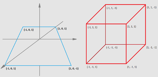
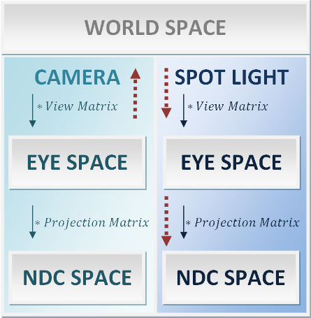
If we are rendering a geometry from the spot light’s point of view (to get depth values which are then stored in the shadowMap texture), then we need to sample the texture to get the depth value of a specific fragment, but this time the camera’s point of view is taken into account. We have to somehow convert one space into another. And this is why we are calculating the outputViewToTextureMatrix matrix.

A bias matrix helps us with converting coordinates from eye space (from a range <-1, 1>) to values from texture coordinates range: <0, 1>.

/* Bias matrix used to map values from a range <-1, 1> (eye space coordinates) to <0, 1> (texture coordinates). */
const mat4 biasMatrix = mat4(0.5, 0.0, 0.0, 0.0,
0.0, 0.5, 0.0, 0.0,
0.0, 0.0, 0.5, 0.0,
0.5, 0.5, 0.5, 1.0);
outputViewToTextureMatrix = biasMatrix * lightProjectionMatrix * lightViewMatrix * inverse(cameraViewMatrix);

The whole idea is represented with the schema shown below.

ShadowMappingMatrixSchema.png
Converting camera eye space to spot light NDC space schema.

When we get this value, we are ready to issue the fragment shader operations. There is directional lighting implemented, which should be clear for a reader. There are also spot light calculations issued.

Fragment shader code

precision highp float;
precision highp sampler2DShadow;
in vec4 outputLightPosition; /* Vector of the spot light position translated into eye-space. */
in vec3 outputNormal; /* Normal vector for the coordinates. */
in vec4 outputPosition; /* Vertex coordinates expressed in eye space. */
in mat4 outputViewToTextureMatrix; /* Matrix we will use in the fragment shader to sample the shadow map for given fragment. */
uniform vec4 colorOfGeometry; /* Colour of the geometry. */
uniform vec3 lightDirection; /* Normalized direction vector for the spot light. */
uniform sampler2DShadow shadowMap; /* Sampler of the depth texture used for shadow-mapping. */
out vec4 color; /* Output colour variable. */
#define PI 3.14159265358979323846
/* Structure holding properties of the directional light. */
struct DirectionalLight
{
float ambient; /* Value of ambient intensity for directional lighting of a scene. */
vec3 color; /* Colour of the directional light. */
vec3 direction; /* Direction for the directional light. */
};
/* Structure holding properties of spot light. */
struct SpotLight
{
float ambient; /* Value of ambient intensity for spot lighting. */
float angle; /* Angle between spot light direction and cone face. */
float spotExponent; /* Value indicating intensity distribution of light. */
float constantAttenuation; /* Value of light's attenuation. */
float linearAttenuation; /* Value of linear light's attenuation. */
float quadraticAttenuation; /* Value of quadratic light's attenuation. */
vec3 direction; /* Vector of direction of spot light. */
vec4 position; /* Coordinates of position of spot light source. */
};
void main()
{
DirectionalLight directionalLight;
directionalLight.ambient = 0.01;
directionalLight.color = vec3(1.0, 1.0, 1.0);
directionalLight.direction = vec3(0.2, -1.0, -0.2);
SpotLight spotLight;
spotLight.ambient = 0.1;
spotLight.angle = 30.0;
spotLight.spotExponent = 2.0;
spotLight.constantAttenuation = 1.0;
spotLight.linearAttenuation = 0.1;
spotLight.quadraticAttenuation = 0.9;
spotLight.direction = lightDirection;
spotLight.position = outputLightPosition;
/* Compute distance between the light position and the fragment position. */
float xDistanceFromLightToVertex = (spotLight.position.x - outputPosition.x);
float yDistanceFromLightToVertex = (spotLight.position.y - outputPosition.y);
float zDistanceFromLightToVertex = (spotLight.position.z - outputPosition.z);
float distanceFromLightToVertex = sqrt((xDistanceFromLightToVertex * xDistanceFromLightToVertex) +
(yDistanceFromLightToVertex * yDistanceFromLightToVertex) +
(zDistanceFromLightToVertex * zDistanceFromLightToVertex));
/* Directional light. */
/* Calculate the value of diffuse intensity. */
float diffuseIntensity = max(0.0, -dot(outputNormal, normalize(directionalLight.direction)));
/* Calculate colour for directional lighting. */
color = colorOfGeometry * vec4(directionalLight.color * (directionalLight.ambient + diffuseIntensity), 1.0);
/* Spot light. */
/* Compute the dot product between normal and light direction. */
float normalDotLight = max(dot(normalize(outputNormal), normalize(-spotLight.direction)), 0.0);
/* Shadow. */
/* Position of the vertex translated to texture space. */
vec4 vertexPositionInTexture = outputViewToTextureMatrix * outputPosition;
/* Normalized position of the vertex translated to texture space. */
vec4 normalizedVertexPositionInTexture = vec4(vertexPositionInTexture.x / vertexPositionInTexture.w,
vertexPositionInTexture.y / vertexPositionInTexture.w,
vertexPositionInTexture.z / vertexPositionInTexture.w,
1.0);
/* Depth value retrieved from the shadow map. */
float shadowMapDepth = textureProj(shadowMap, normalizedVertexPositionInTexture);
/* Depth value retrieved from drawn model. */
float modelDepth = normalizedVertexPositionInTexture.z;
/* Calculate vector from position of light to position of fragment. */
vec3 vectorFromLightToFragment = vec3(outputPosition.x - spotLight.position.x,
outputPosition.y - spotLight.position.y,
outputPosition.z - spotLight.position.z);
/* Calculate cosine value of angle between vectorFromLightToFragment and vector of spot light direction. */
float cosinusAlpha = dot(spotLight.direction, vectorFromLightToFragment) /
(sqrt(dot(spotLight.direction, spotLight.direction)) *
sqrt(dot(vectorFromLightToFragment, vectorFromLightToFragment)));
/* Calculate angle for cosine value. */
float alpha = acos(cosinusAlpha);
/*
* Check angles. If alpha is less than spotLight.angle then the fragment is inside light cone.
* Otherwise the fragment is outside the cone - it is not lit by spot light.
*/
const float shadowMapBias = 0.00001;
if (alpha < spotLight.angle)
{
if (modelDepth < shadowMapDepth + shadowMapBias)
{
float spotEffect = dot(normalize(spotLight.direction), normalize(vectorFromLightToFragment));
spotEffect = pow(spotEffect, spotLight.spotExponent);
/* Calculate total value of light's attenuation. */
float attenuation = spotEffect /
(spotLight.constantAttenuation +
spotLight.linearAttenuation * distanceFromLightToVertex +
spotLight.quadraticAttenuation * distanceFromLightToVertex * distanceFromLightToVertex);
/* Calculate colour for spot lighting.
* Scale the colour by 0.5 to make the shadows more obvious. */
color = color / 0.5 + (attenuation * (normalDotLight + spotLight.ambient));
}
}
/* Angle (in radians) between the surfaces normal and the light direction. */
float angle = acos(dot(normalize(outputNormal), normalize(spotLight.direction)));
/*
* Reduce the intensity of the colour if the object is facing away from the light.
* scaleIntensity is 1 when the light is facing the surface, 0 when its facing the opposite direction.
*/
float scaleIntensity = smoothstep(0.0, PI, angle);
vec4 scaleVector = vec4(scaleIntensity, scaleIntensity, scaleIntensity, 1.0);
color *= scaleVector;
}

The main idea behind this is simple: we take a fragment, check, whether it is placed inside the spot light cone (with checking the angle between the fragment and the spot light direction). Then the fragment is considered as lit by a spot light, or outside: in this case no spot light is added to a fragment. In the situation when a fragment is lit by the spot light, we need to check whether it should be obscured by a shadow.

This is where the previously calculated outputViewToTextureMatrix matrix will be used. We need to sample the depth texture with properly calculated coordinates for a given fragment and compare the retrieved value with the model depth. In the comparison there is also a shadowMapBias added to avoid artefacts.