Video file streaming interface. More...
Content | |
| Video Driver API Functions | |
| Video Driver API functions. | |
| Video Driver API Defines | |
| Video Driver API Definitions. | |
Data Structures | |
| struct | VideoDrv_Status_t |
| Video Status. More... | |
Video file streaming interface.
Video streaming use case is implemented for AVH FVPs based on the general-purpose Virtual Streaming Interface (VSI).
The use of generic Video Driver APIs simplifies re-targeting of the application code between virtual and physical devices.
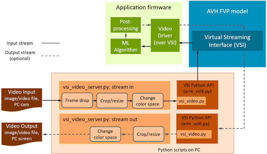
The video driver implementation for AVH FVPs relies on the VSI peripheral API with an interface to the python scripts. For video use case the python scripts access local video or image files as streaming input/output. Alternatively, PC's camera can be used as video input and PC's display as video output.
The operation of the video driver follows the principles used in the drivers for real hardware: application should configure the driver with such parameters as resolution, frame rate, color scheme. Additionally it specifies the local input/output file name or defaults to webcam input. Then the application controls the video stream / frame extraction from the peripheral.
The concept is shown on the figure below for input and optional output streams:
Additional details are provided in Operation details.

In addition to the requirements listed in Python environment setup, the VSI Video use case also requires installed OpenCV Python package. Run the following command to install it with pip:
The table below lists the files that implement the video over VSI peripheral:
| Item | Description |
|---|---|
| ./interface/video/include/video_drv.h | Video Driver API header file. Used by implementations on AVH FVPs and real HW boards. |
| ./interface/video/source/video_drv.c | Video driver implementation for AVH FVPs. |
| ./interface/video/python/arm_vsi4.py | Video via VSI Python script for video input channel 0. |
| ./interface/video/python/arm_vsi5.py | Video via VSI Python script for video output channel 0. |
| ./interface/video/python/arm_vsi6.py | Video via VSI Python script for video input channel 1. |
| ./interface/video/python/arm_vsi7.py | Video via VSI Python script for video output channel 1. |
| ./interface/video/python/vsi_video.py | VSI video client module. |
| ./interface/video/python/vsi_video_server.py | VSI video server module. |
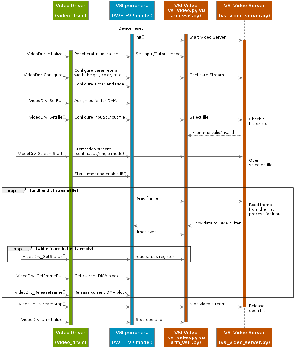
The execution flow for video input on channel 0 is explained in the diagram below:

| struct VideoDrv_Status_t |
Video Status.
Structure with information about the Video channel status. The data fields encode active and buffer state flags.
Returned by: